


Special offers from our partners!

Find Replacement BBQ Parts for 20,308 Models. Repair your BBQ today.

480-1081 16 4-03
North Star
EPA Certied Fireplace
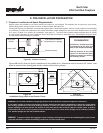
WARNING!
Maintain a minimum of 2” air clearance to all parts of the
chimney system at all times! Failure to maintain this 2” air
clearance will cause a structure re.
NOTE: You must provide support for the pipe during construction
and check to be sure inadvertent loading has not dislodged the
chimney section from the replace or at any chimney joint.
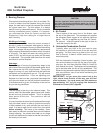
WARNING!
When chimney sections exceeding six feet in length
are installed between an offset and return, structural
support must be provided to reduce off-center loading
and prevent chimney sections from separating at the
chimney joints.
FIRESTOP
JOINT BAND
(OPTIONAL)
STRAPS
OPTIONAL
ADDITIONAL
SUPPORT
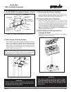
Figure 16B - Offset/Return with Stabilizer
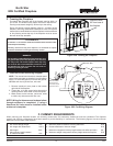
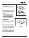
10 Securing the Chimney System
When offsets and returns are joined to straight pipe sections,
they must be locked into position with the screws provided
(outer only), using the predrilled holes. To prevent gravity
from pulling the chimney sections apart, the returns and the
chimney stabilizers have straps for securing these parts to
joists or rafters. See Figure 16B.
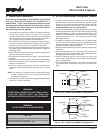
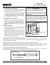
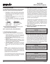
11.Marking the Exit Point of the Roof
Locate the point where the chimney will exit the roof by
plumbing down to the center of the chimney. Drive a nail up
through the roof to mark the center. See Figure 16C.
12.Cutting out the Hole in the Roof
Measure to either side of the nail 7-1/4” and mark the
14-1/2” x 14-1/2” opening required. This is measured on the
horizontal; actual length may be larger depending on the pitch
of the roof. Cut out and frame the opening. See Chapter 25 of
the Uniform Building Code for Roof Framing Details.
Be sure to maintain a 2” minimum air space between the
chimney section and the roof.
13.Assembling the Chimney Sections
Through the Roof
Continue to add chimney sections through the roof opening,
maintaining at least a 2” air space.
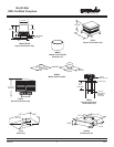
Figure 16C - Ceiling/Attic Construction
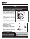
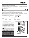
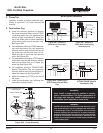
9. SL-300 MH842 Celing/Roof Thimble
(Cont’d)
NAIL
FLASHING
PLATE
CHIMNEY
THIMBLE
EXTENSION
SCREW
FLASHING
THIMBLE
A
DJUSTABLE
EXTENSION
HOLES
Figure 16A - Installing an MH842 Conguration 3