


Special offers from our partners!

Find Replacement BBQ Parts for 20,308 Models. Repair your BBQ today.
4-03 13 480-1081
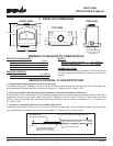
North Star
EPA Certied Fireplace
WARNING!
Before starting, do the following:
1. Wear gloves and safety glasses for protection.
2. Keep hand tools in good condition. Sharpen cutting edges and make sure tool handles are secure.
3. Always maintain the minimum air space required to the enclosure to prevent re.
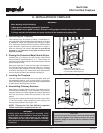
G. INSTALLATION OF FIREPLACE
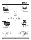
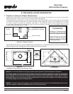
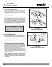
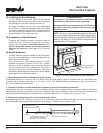
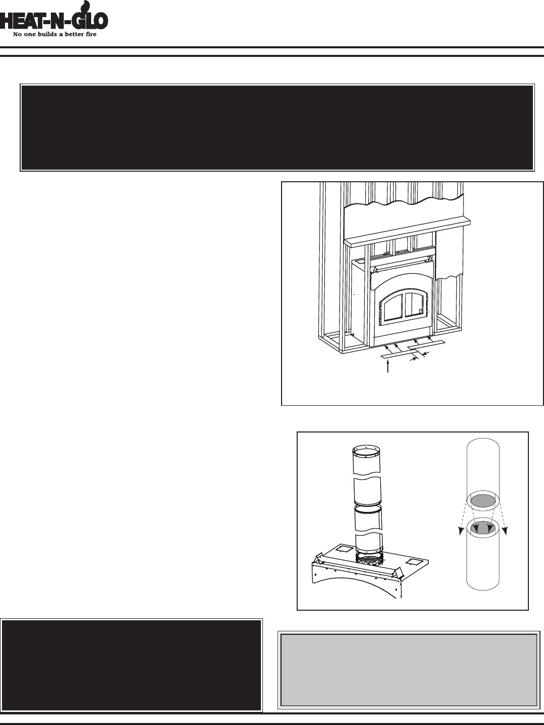
1" OVERLAP
Metal strips 2" under edge of
Fireplace and Hearth Extension and
2" on both side of fireplace opening
Figure 13A - Positioning the Metal Strips
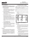
1. Positioning the Fireplace
This fireplace may be placed on either a combustible or
noncombustible continuous at surface, depending on the type
of installation. Follow the instructions for framing on pages
9-10 and Hearth Extension/Floor Protection Requirements
under Minimum Clearances to Combustibles on page 5.
Slide the fireplace into position. Be sure to provide the
minimum 1” air clearance at the sides and back of the
replace assembly.
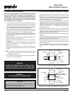
3. Leveling the Fireplace
L
evel the replace side-to-side and front-to-back. Shim with
noncombustible material, such as sheet metal, as necessary.
Secure the replace (using the pallet mounting brackets located
on either side of the replace) to the oor.
2. Placing the Protective Metal Hearth Strips
Included with your replace you will nd two metal hearth
strips measuring approximately 23” x 4”. These strips are
used to provide added protection where the replace and the
hearth extension meet.
Slide each metal strip 2” under the front edge of the replace.
The individual pieces must overlap each other by 1” minimum
in the middle of the replace to provide continuous coverage
of the oor. See Figure 13A. These metal strips should extend
from the front and sides of the replace opening by 2”.
WARNING!
Carefully follow the instructions for assembly of the
pipe and other parts needed to install this fireplace
system. Failure to do so may result in a re, especially
if combustibles are too close to the replace or chimney
and air spaces are blocked, preventing the free movement
of cooling air.
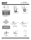
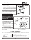
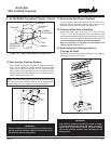
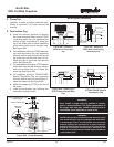
4. Assembling Chimney Sections
Attach either a straight chimney section or an offset to the top
of the replace (depending on your installation requirement).
Chimney sections are locked together by pushing downward
until the top section meets the stop bead on the lower
section.
The inner ue is placed to the inside of the ue section below
it. The outer casing is placed outside the outer casing of the
chimney section below it. See Figure 13B.
NOTE: Chimney Air Kit, Part CAK4A is required.
Follow instructions supplied with the kit.
Figure 13B-Assembling Chimney Sections
CAUTION:
Inner ue and outer liner sections cannot be disassembled
once locked together. Plan ahead to ensure the proper
installation height is achieved with the selected chimney
components.