


Special offers from our partners!

Find Replacement BBQ Parts for 20,308 Models. Repair your BBQ today.

©Titan Tool Inc. All rights reserved. 27
EnglishFrançaisEspañol
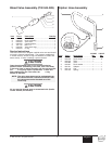
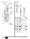
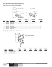
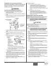
Accessories and Service Kits
These items may be purchased separately from your local
Speeflo distributor.
Part #
Description
103-826 5 Gal. Siphon Hose Assembly w/Rock Catcher
1" x 4.5'
103-827 55 Gal. Siphon Hose Assembly w/Rock Catcher
1" x 6.5'
103-627 Rock Catcher
930-005 Paint Filter Element, 5 Mesh (for multicolors
and heavy materials)
930-006 Paint Filter Element, 50 Mesh (for latex and
normal architectural materials)
930-007 Paint Filter Elements, 100 Mesh (for stains,
lacquers and fine materials)
520-050 SGX-20 G, T, and 1/4” Hose Kit
520-051 SGX-20 G, T, and 3/8” Hose Kit
101-208 Grounding Clamp
101-212 Grounding Wire, 12 Gauge x 25'
700-925 Piston Lube
430-362 Coolflo™ Hydraulic Fluid, 1 Quart
430-361 Coolflo™ Hydraulic Fluid, 1 Gallon
143-050 Fluid Section Service Kit — Minor
930-050 Filter Service Kit
944-050 Bleed Valve Service Kit
975-212 2-Gun Manifold with Ball Valves, 1/4"
975-213 3-Gun Manifold with Ball Valves, 1/4"
975-312 2-Gun Manifold with Ball Valves, 3/8"
975-313 3-Gun Manifold with Ball Valves, 3/8"
Airless Tip Selection
Tips are selected by the orifice size and fan width. The proper
selection is determined by the fan width required for a specific
job and by the orifice size that will supply the desired amount
of fluid and accomplish proper atomization.
For light viscosity fluids, smaller orifice tips generally are
desired. For heavier viscosity materials, larger orifice tips are
preferred. Please refer to the chart below.
The following chart indicates the most common sizes and the
appropriate materials to be sprayed.
Fan widths measuring 8" to 12" (20 to 30 cm) are most
preferred because they offer more control while spraying and
are less likely to plug.
Tip Size Spray Material Filter Type
.011 – .013 Laquers and stains 100 mesh filter
.015 – .019 Oil and latex 50 mesh filter
.021 – .026 Heavy bodied latex and blockfillers 5 mesh filter
NOTE: Do not exceed the pump's recommended tip
size.
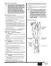
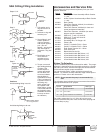
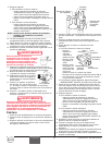
SAE O-Ring Fitting Installation
Steps 1 & 2:
Step 3:
Step 4:
Step 5:
Cautions:
Lubricate
Lubricate
Tighten nut
Recess
gap
No gap
Align
Hold
this part
stationay
Avoid screwing fitting in too far.
Avoid leaving fitting too far out.
Bent washer allows
for o-ring extrusion
O-ring cut on
thread
1. Pull washer and o-
ring back as far as
possible.
2. Lubricate o-ring and
entrance port.
3. Screw fitting in until
washer pushes o-
ring into entrance
and sits flat against
port. (Do not
tighten! - only do this
step hand tight to
compress o-ring into
port!)
4. Back fitting out no
more than one
complete turn to
align as required.
5. Torque nut wrench
tight holding backup
on fitting. This
should expose a
recess gap behind
the nut which can
act as an indicator
that the fitting is
assembled correctly.
(This is a feature for
a specific version of
this fitting only -
which screws into
the cylinder head.
Other fittings, as the
ones which attach to
the hydraulic pump,
assemble the same
but may not have
the indicator.)