


Special offers from our partners!

Find Replacement BBQ Parts for 20,308 Models. Repair your BBQ today.

©Titan Tool Inc. All rights reserved. 25
English
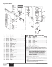
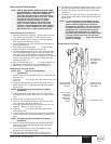
Servicing the Fluid Section
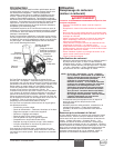
Disassembling the Fluid Section
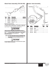
1. Remove siphon tube assembly. Unthread the foot valve
(15) and the pump cylinder (11) with a strap wrench.
2. Slide the retaining ring (1) up with a small screwdriver,
then push the connecting pin (2) out.
3. Pull the displacement rod (6) through the lower cavity of
the motor/pump block.
4. Remove the motor/pump block, 37)( o-ring (3), upper
packing spring (5), and upper packing set (4).
5. Hold the displacement rod (6) in a vise by the flats at the
top of the displacement rod and remove the piston seat
(10) with a wrench while holding the displacement rod
horizontal with wooden support, if necessary. Remove the
ball (9), lower packing set (4), lower packing spring (8),
and spring retainer (7).
6. Remove the ball cage (13), 37)( o-ring (3), and ball (14).
7. Replace the connecting pin (2) and retaining ring (1) .
8. Remove the o-ring (12) from the pump cylinder (11)
Reassembling the Fluid Section
1. Place the ball (14) into the foot valve (15), followed by the
ball cage (13).
2. Insert the 37)( o-ring (3) into the lower groove of the foot
valve (15).
3. Place the lower packing set (4) onto the piston seat (10)
with the peak of the “V” packings pointing down toward
the foot valve.
4. Clean the threads on the piston seat (10) and coat the
threads with blue Loctite. Make sure no Loctite is on the
seat.
5. Place the ball (9) onto the piston seat (10).
6. Place the lower packing spring (8) onto the piston seat
(10), followed by the spring retainer (7).
7. Screw the displacement rod (6) and the piston seat (10)
together. Tighten in a vise to 75 ft./lbs.
8. Insert the 37)( o-ring (3) into the upper grove of the
motor/pump block.
9. Insert the upper packing set (4) into the motor/pump block
with the peak of the “V” packings pointing up toward the
motor.
10. Place the upper packing spring (5) into the motor/pump
block with the small tapered end facing up toward the
motor/pump block.
11. Insert the displacement rod (6) up through the upper
packings in the motor/pump block.
12. Align the holes in the displacement rod (6) and the
hydraulic piston rod and insert the connecting pin (2).
NOTE: The packings must be soaked in oil before
installation.
NOTE: The packings must be soaked in oil before
installation.
NOTE: Use 37)( tape on all threaded pipe
connections.
NOTE: USE OF NON-SPEEFLO SERVICE PARTS MAY
VOID WARRANTY. ASK FOR ORIGINAL PARTS
MADE BY SPEEFLO FOR BEST SERVICES.
This pump should receive a routine servicing
after approximately 1,000 hours of use. Earlier
servicing is required if there is excessive
leakage from the top packing or if pump
strokes become faster on one stroke or the
other. The use of Speeflo Piston Lube (P/N
700-925) is recommended as an upper packing
lubricant. DO NOT SUBSTITUTE OIL, WATER,
OR SOLVENT for an upper packing lubricant.
13. Thread the short threads of the pump cylinder (11) into
the motor/pump block and tighten with a strap wrench.
14. Place the o-ring (12) onto the top grove of the pump
cylinder (11).
15. Thread the foot valve (15) onto the pump cylinder (11),
tighten with a strap wrench, then back off to align the
siphon hose.
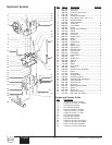
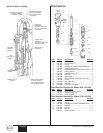
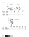
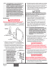
Fluid Section Cut-Away
Peaks of upper
packings must
face up.
Torque piston
retainers to
75 ft./lbs.
(1095 N/m).
Use blue
Loctite.
Oil cup area
for piston lube
packing
lubricant.
Peaks of lower
packings must
face down.
Lubricate O-ring.
NOTE: It is not necessary to over-tighten the foot
valve. O-ring seals perform sealing function
without excessive tightening. Full thread
engagement is sufficient. The foot valve may
be rotated backward up to 1/2 turn from full
engagement for convenient hose position.
For siphon hose attachment, it is critically
important that the threads of the siphon hose
fit snugly into the foot valve with the hose
assembly couplings 37)( taped and sealed to
prevent air leakage.