


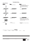
Special offers from our partners!

Find Replacement BBQ Parts for 20,308 Models. Repair your BBQ today.

©Titan Tool Inc. All rights reserved. 23
English
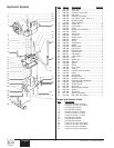
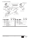
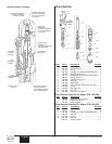
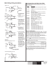
3. Place the motor/pump assembly in a vise, holding it
securely by the motor/pump block (25).
4. Remove cylinder head plug (7).
5. Loosen lock ring (22) with a spanner wrench and unthread
tube retaining nut on tee (27). Loosen tube retaining nut
on elbow (15). Slide the nut down. Push motor tube (26)
into tee (27) far enough to clear elbow (15). Slowly
unthread cylinder head (11) and Iift it just high enough
above the cylinder (23) to reach the valve rod assembly
(20) with vise grip pliers.
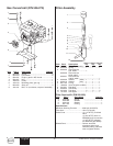
6. The piston rod (21) should be near the top of its stroke for
disassembly. It may be necessary to use a wood or nylon
driver to push the piston rod up to its top position.
7. Grip the valve rod securely with vise grip pliers and then
remove the FlexLoc nut (9) from the top of the valve rod
assembly (20). Be careful that spool (5) does not fall. The
cylinder head (11) can now be lifted off. Unthread the
cylinder (23) from the motor/pump block (25). Note: An
extra lock ring (22) can be used to jam the two lock rings
together on the cylinder and a pipe wrench can be used to
unthread the cylinder (23) from the motor/pump block
(25).
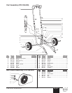
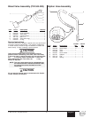
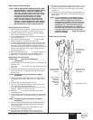
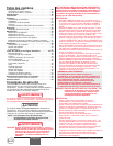
8. To remove the
connecting pin, slide
the retaining ring
down with a small
screwdriver, and
then push the
connecting pin out.
9. Remove the piston
rod assembly from
the motor/pump
block (25).
10. Remove rod seal (24), being extremely careful not to
scratch the seal groove in the motor/pump block (25).
11. Place the piston retainer screw (16) on the piston rod
assembly in a vise. Slide a long bar through the hole at
the base of the piston rod for leverage, and unthread the
piston rod from the piston retainer screw.
12. Remove piston (17) and lift out valve rod assembly (20).
13. Remove piston seal (18) and o-ring (19).
14. Remove trip retainers (1), trip springs (3), and balls (4)
from cylinder head (11). Remove o-rings (2) from trip
retainers (1).
15. Remove retaining ring (14) and sleeve retainer (13).
Gently tap spool/sleeve set (5) out of cylinder head (11)
using a wood or nylon rod.
16. Inspect piston rod (21) and cylinder (23) for wear,
scratches, and dents. Replace if damaged.
17. Inspect spool valve (5) for wear. Replace if necessary.
spool valve should move smoothly and freely with no
force by holding in a vertical position. If it does not, it can
cause the motor to stall.
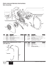
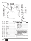
Reassembling the Hydraulic Motor
1. Separate spool/sleeve set (5). Place o-rings (6) onto
sleeve. Lubricate o-rings with hydraulic oil. Gently push the
sleeve into cylinder head (11) with the flatter side of the
sleeve facing out. Use a nylon rod to tap sleeve down until
it reaches its full depth. Do not use any other type of tool
that might damage or leave particles or residue on the
sleeve. Install the spool through the top of the cylinder
head, down into the sleeve.
Do not use Piston Lube pump packing lubricant. It is a
solvent and will severely damage seals and O-Rings of the
hydraulic motor.
2. Install o-rings (2) on trip retainers (1). Install trip retainer
balls (4) followed by springs (3) which, when installed, will
hold spool/sleeve set (5) in proper place for assembly.
CAUTION
Connecting
Pin
Retaining
Ring
3. Install sleeve retainer (13) followed by snap ring (14) into
cylinder head (11), which will hold valve sleeve in place.
Install o-ring (12) in the o-ring groove of the cylinder head.
4. Replace lower seal (24) in motor/pump block (25). Be
sure the open portion of the seal is facing upward (V).
This seal requires no special tool.
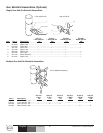
5. Place piston rod (21) in vise. Inspect valve rod assembly
(20) for any damage. Make sure the lock nut at the
bottom of the valve rod assembly (20) is secure. DO NOT
remove. Then, place into piston rod (21) as illustrated.
Install o-ring (19), lubricating it well and replacing piston
(17) onto piston rod (21). Put one drop of blue Loctite on
the piston retainer screw (16). Tighten piston retainer
screw until piston is locked into place. Check valve rod
assembly (20) for normal spring action at this time.
6. Install piston seal (18) with lips facing downward.
Carefully install o-ring (19). Expand the ring and stretch it
sufficiently for installation.
7. With motor/pump block (25) still in vise, install lower seal
(24) by pushing it towards its groove with a properly sized
blunt rod. Then complete installation with the fingers. No
tool is necessary. Do not twist the seal.
8. Pre-lubricate the piston and valve rod assembly with
Coolflo™ hydraulic fluid (P/N 430-361). Install piston rod
(21) into motor/pump block (25) with a gently pushing and
rotating motion to work the piston rod in through the seal
(24).
9. Replace the connecting rod pin and retainer ring.
10. Install o-ring (12) on cylinder wall. Lubricate ring and inner
wall. With the piston rod held firmly, the cylinder should
be gently driven over the piston seal with a rubber mallet.
Tightly thread the cylinder into motor/pump block (25).
11. Raise piston rod (21) to top position and thread lock ring
(22) all the way up on upper threads of cylinder (23).
12. Pull valve rod assembly (20) up as far as it will travel and
grasp it with vise grip pliers. Then install cylinder head
(11), already assembled, over valve rod until the top
threads of the valve rod pass through the top of the
spool/sleeve set (5). The valve rod threads must be clean
and free of oil. Place one drop of blue Loctite on threads
of flex lock nut (9) and thread nut onto valve rod to full
tight position (do not over-tighten) while holding valve rod
below with vise grip pliers.
13. Thread cylinder head (11) down onto the cylinder (23) and
then back off just enough to reassemble hydraulic fittings
and motor tube (26). Tighten lock ring with spanner
wrench to hold cylinder head in position.
14. The tee assembly (27) and the elbow (15) use an o-ring
(28) to seal on the outer diameter (O.D.) of the motor tube
(26). The O.D. of the motor tube should be free of
scratches or sharp edges. The lock nuts on these fittings
first should be hand tightened, then wrench tightened
another half turn.
15. Install o-ring (8) onto cylinder head plug (7). Tighten.
NOTE: Inspect the bottom of piston rod (21) for nicks
or sharp areas that could damage the piston
seal during installation through the
motor/pump block (25).