


Special offers from our partners!

Find Replacement BBQ Parts for 20,308 Models. Repair your BBQ today.

Heat & Glo • Crescent II • 2083-902 Rev. G • 9/0540
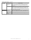
A. Intellifire Ignition System
Symptom Possible Causes Corrective Actions
1. The
ignitor/module
makes noise, but no
spark.
a. Incorrect wiring. Verify "S" wire (white) for sensor and "I" wire (orange) for ignitor are
connected to correct terminals on module and pilot assembly. Reversed wires
at the module may cause system to make sparking noise, but spark may not
be present at pilot hood.
b. Loose
connections or
electrical shorts in
the wiring.
Verify no loose connections or electrical shorts in wiring from module to pilot
assembly. Rod closest to pilot hood should be ignitor. Verify connections
underneath pilot assembly are tight; also verify connections are not grounding
out to metal chassis, pilot burner, pilot enclosure, mesh screen if present, or
any other metal object.
c. Ignitor gap is too
large.
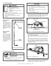
Verify gap of igniter to pilot hood. The gap should be approximately .17 inch
or 1/8 inch.
d. Faulty module. Turn ON/OFF rocker switch or wall switch to OFF position. Remove ignitor
wire "I" from module. Place ON/OFF Rocker switch or wall switch in ON
position. Hold ground wire about 3/16 inch away from "I" terminal on module.
If there is no spark at "I" terminal module must be replaced. If there is a spark
at "I" terminal, module is fine. Inspect pilot assembly for shorted sparker wire
or cracked insulator around electrode.
2. Pilot won't light,
there is no noise or
spark.
a. Transformer
installed correctly.
Verify that transformer is installed and plugged into module. Check voltage of
transformer under load at spade connection on module with ON/OFF switch
in ON position. Acceptable readings of a good transformer are between 3.2
and 2.8 volts AC.
b. A shorted or
loose connection in
wiring configuration
or wiring harness.
Remove and reinstall the wiring harness that plugs into module. Verify there is
a tight fit. Verify pilot assembly wiring to module. Remove and verify continuity
of each wire in wiring harness.
c. Improper wall
switch wiring.
Verify that 110/VAC power is "ON" to junction box.
d. Module not
grounded.
Verify black ground wire from module wire harness is grounded to metal
chassis of appliance.
e. Faulty module. Turn ON/OFF rocker switch or wall switch to OFF position. Remove ignitor
wire "I" from module. Place ON/OFF Rocker switch or wall switch in ON
position. Hold ground wire about 3/16 inch away from "I" terminal on module.
If there is no spark at "I" terminal module must be replaced. If there is a spark
at "I" terminal, module is fine. Inspect pilot assembly for shorted sparker wire
or cracked insulator around electrode.
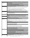
3. Pilot lights but
continues to spark,
and main burner will
not ignite. (If the
pilot continues to
spark after the pilot
flame has been lit,
flame rectification
has not occurred.)
a. A shorted or
loose connection in
sensor rod.
Verify all connections to wiring diagram in manual. Verify connections
underneath pilot assembly are tight. Verify connections are not grounding out
to metal chassis, pilot burner, pilot enclosure or screen if present, or any other
metal object.
b. Poor flame
rectification or
contaminated
sensor rod.
Verify that flame is engulfing sensor rod. If the pilot assembly does not have a
ground strap, consider installing one to increase flame rectification. Verify
correct pilot orifice is installed and inlet gas specifications. Flame carries
rectification current, not the gas. If flame lifts from pilot hood, the circuit is
broken. A wrong orifice or too high an inlet pressure can cause pilot flame to
lift. The sensor rod may be contaminated. Clean sensor rod with emery cloth.
c. Module is not
grounded.
Verify that module is securely grounded to metal chassis of appliance. Verify
that wire harness is firmly connected to module.
Troubleshooting
14
With proper installation, operation, and maintenance your gas appliance will provide years of trouble-free service. If you do
experience a problem, this troubleshooting guide will assist a qualified service person in the diagnosis of a problem and the
corrective action to be taken. This troubleshooting guide can only be used by a qualified service technician.