


Special offers from our partners!

Find Replacement BBQ Parts for 20,308 Models. Repair your BBQ today.
Heat & Glo • Crescent II • 2083-902 Rev. G • 9/0530
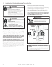
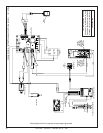
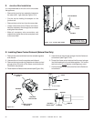
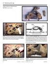
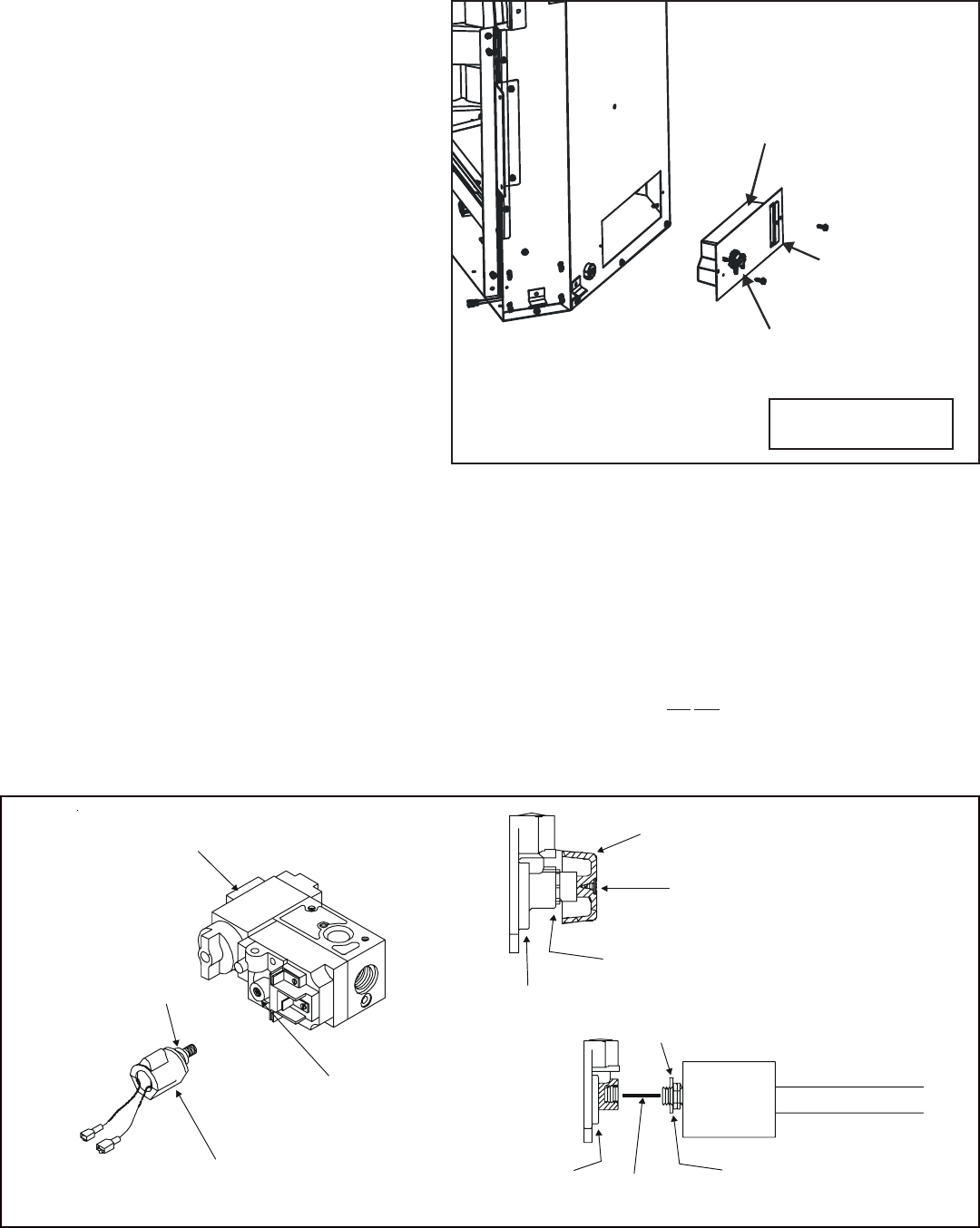
D. Junction Box Installation
It is recommended to wire the unit from outside
the appliance.
• Remove the junction box assembly located on
the outer shell - right side (see Figure 10.3).
• Cut the zip ties holding the adaptor on the
junction box.
• Remove the junction box from the cover plate.
• Loosen two screws on the Romex connector,
feed the necessary wire through the connector
and tighten the screws.
• Make all necessary wire connections and
reattach the junction box to the cover plate and
to the outer shell.
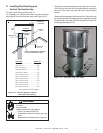
Figure 10.3 Junction Box Detail
NOTE: Do NOT wire
110VAC to wall switch.
JUNCTION BOX
COVER
PLATE
ROME
X
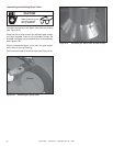
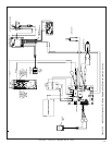
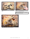
Figure 10.4
1
. Remove the screw and knob from the variable regulator
and discard.
2. Unscrew the nut from the regulator and discard.
3. Remove the bag containing a washer and blue and red
plungers from the side of the flame control solenoid.
Discard the red plunger.
4. Place washer on flame control solenoid (see Figure 10.4).
5. Insert the blue (natural gas) plunger into the flame con-
trol solenoid (see Figure 10.4).
6. Thread the flame control solenoid with correct plunger
into the thread hole in the variable regulator. Turn one to
two turns only. Do not tighten or damage may occur.
7. Connect orange wires from control box to the flame con-
trol solenoid.
VARIABLE
REGULATOR
GAS CONTROL
VALVE
FLAME CONTROL
SOLENOID
KNOB
SCREW
NUT
VARIABLE REGULATOR
JAM NUT
VARIABLE
REGULATOR
SOLENOID
WASHER
WASHER
PLUNGER
E. Installing Flame Control Solenoid (Natural Gas Only)