


Special offers from our partners!

Find Replacement BBQ Parts for 20,308 Models. Repair your BBQ today.

39
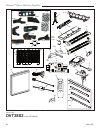
Chateau™ Direct Vent Gas Fireplace
20011957
CO134
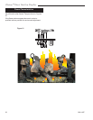
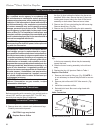
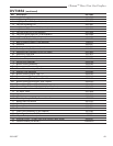
AF pilot orifice
3/07
Index Tab
Snap Ring
Allen Wrench
CO134
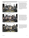
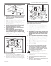
Fig. 56 Remove pilot orifice.
1. Remove two (2) screws holding the pilot assembly
to the burner assembly. Move the pilot assembly
toward the back wall.
2. Using a back-up wrench, disconnect the gas supply
fitting near the right rear corner of the firebox.
3. Remove four (4) screws holding the burner assem-
bly to the firebox floor.
4. Carefully slide the burner assembly out of the way.
5. Remove 13 screws around the perimeter holding
large access panel on the of the firebox.
6. Carefully pull back the panel just enough to gain
access to control box.
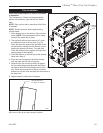
7. Locate the black plastic cap on the gas valve.
(Fig. 57) Remove the black cap by pulling the cap
straight off. Note the position of the marker on the
top of the rotary knob. This marker will point to NAT
or LP. (Fig. 58)
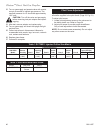
8. To convert the valve from NG to LP, push in the
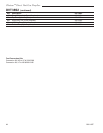
Black Plastic Cap
Minimum Rate
Screw
CO138
Fig. 57 AF4000 Valve in place.
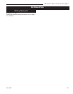
Minimum Rate
Screw
CO137
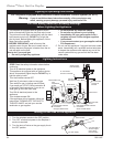
Fig. 58 Remove black plastic cap and adjust rotary knob to
correct gas type. (LP position shown) Replace minimum rate
screw with one supplied in conversion kit.
Gas Type
Marker
Pilot Adjustment Screw
knob and rotate 90° (1/4 turn). NOTE: The shaft
should point to LP. The shaft will remain pushed-in.
9. Remove the slotted brass minimum rate screw lo-
cated in the valve next to the motor drive. (Fig. 58)
10. Replace the minimum rate screw with the one
provided in the LP conversion kit supplied with this
fireplace. Ensure the screw is fully installed.
11. Install the enclosed identification label to the valve
body where it can be easily seen.
12. Reinstall steel panel.
13. Reinstall burner to original position. Reinstall burner
leg, burner tube and fettle. Re-attach supply tube to
gas supply fitting. Using a back-up wrench, tighten
securely.
14. Test for leaks. Apply electric and gas to the system.
15. Light the pilot burner using the remote control. With
soapy solution check for leaks around the pilot as-
sembly where the tube enters the pilot assembly.
Tighten fitting if necessary.
16. Light the main burner and check for leaks around
the burner supply tube fittings and burner orifices.
Tighten if necessary.
17. Turn fireplace OFF.
18. After the conversion and leak checks have been
made, manifold outlet pressure can be checked
with a manometer at the test ports located at the
side front edge of the fireplace opening. The lower
test port is manifold outlet pressure.
CAUTION: Turn off the gas supply before
removing test port plug.
19. Using a 7/16” nut driver, remove the threaded plug
from the test port.
20. Thread the supplied extension adaptor into the
open test port.
21. Attach a 1/4” diameter pressure gauge flexible hose
fully onto the barb of the adaptor.