


Special offers from our partners!

Find Replacement BBQ Parts for 20,308 Models. Repair your BBQ today.

21
Chateau™ Direct Vent Gas Fireplace
20011957
FP1461
thru wall trim
3/17/04 djt
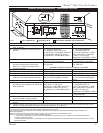
2”
(51mm)
1”
(25mm)
Min.
1” (25mm) Min.
16¹⁄₄” x 16¹⁄₄”
(413 x 413mm)
Opening
FP1461
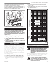
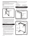
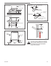
Fig. 24 A 2” (51mm) thick trim is required around opening.
joints as described on Page 16.
Sealing firestop gaps with high temperature sealant
will restrict cold air being drawn in around fire-
place.
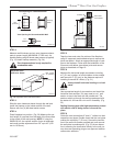
STEP 6
Before installing the termination, a 2” (51 mm) thick trim
or frame is required around the 16¹⁄₄” x 16¹⁄₄” (413 x 413
mm) square opening to allow the vent termination to go
directly onto the elbow. (Fig. 24)
• The control housing must only be installed on an
inside wall.
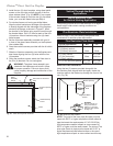
Package contents:
• 1, Glass frame assembly • 2, short machine screws
• 2, Short top brackets • 2, Long machine screws
• 2, Long bottom brackets • 4, sheet metal screws
Installation Procedure
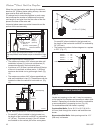
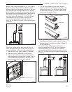
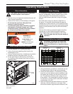
1. If the fireplace is installed flush with the wall, a high
temperature sealant must be applied to seal around
the surround around the glass frame assembly 3/4”
(19 mm) from the front edge of the surround. (Fig.
25)
• • • • • • • • • • • •
• •• •••••• • •••• • •• • ••••••••••••••••••••
• •• • • • • •
3/4"
(19mm)
Glass Frame As-
sembly
High Temperature
Sealant
Surround
FP1480
Fig. 25 Apply high temperature sealant on surround around
glass frame assembly when unit is installed flush with wall.
STEP 7
Guide the vent terminations 8” and 11” collars into their
respective vent pipes. Double check that the vent pipes
overlap the collars by 2” (51 mm). Secure the termina-
tion to the wall with screws provided and caulk around
the wall plate to weatherproof. (Fig. 24) As an alterna-
tive to screwing the termination directly to the wall you
may also use expanding plugs or an approved exterior
construction adhesive.
Installing the 38S2VDK Door
When installing the DVT38S2 on an outside wall, the
following steps must be taken into consideration. Fail-
ure to do so will result in a major reconstruction
and CFM Corporation will not be responsible for
costs associated with incorrect installation.
• If the fireplace is to be installed flush with the wall, a
1/4” (6 mm) clearance is required on both sides and
top of surround around the glass frame assembly in
order for the door to be accessible. (Refer to Page 4,
Fig. 1)
• If the fireplace is recessed 3/4” (19 mm) from the
wall, then no extra clearances are needed around
the surround.
• The fireplace must be installed with the stationary
glass facing the outside (control housing will be
located on the left hand side of the fireplace when
facing the fireplace from inside the house).
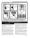
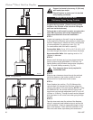
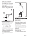
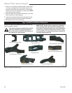
2. Install the two (2) bottom (longer) brackets, using
sheet metal screws, at the bottom right and left cor-
ners of the unit. (Fig. 26)
FP1481
install brackets
4/04
Long Bottom
Bracket
Sheet Metal
Screws
FP1481
Fig. 26 Use sheet metal screws to attach brackets to existing
holes under glass frame assembly.
Short Top
Bracket
Sheet
Metal
Screws
Existing
Door on
Unit
Refer to
Figure xx