


Special offers from our partners!

Find Replacement BBQ Parts for 20,308 Models. Repair your BBQ today.

35
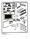
Chateau™ Direct Vent Gas Fireplace
20011957
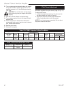
Troubleshooting
If erratic system behavior is observed that cannot be resolved by the methods outlined below, ensure that there is
not a transmitter with batteries installed that may be interfering. If a transmitter is packed with batteries installed, its
buttons may be depressed sending a constant signal which can interfere with the transmission of desired signals. A
transmitter with new batteries can have a range of over 100’ (30.4 m).
American Flame Gas Control System
Module will not learn trans-
mitter
• Ensure the REMOTE/OFF switch on the side of the module is set to REMOTE.
• Make sure the batteries in both the transmitter and receiver are installed in the
proper direction and are not drained. Individual battery voltage should be no less
than 1.4V for AA and AAA batteries, 2.8V for button cells, and 9,0V for 12V batter-
ies.
• Verify the transmitter indicates a signal is being sent. With thermostat transmitters,
the LCD display should indicate ON or OFF depending on which button is being
pressed. The LED indicator should illuminate on wall transmitters and on/off hand-
held transmitters. Buttons should be pressed and held for 1 to 2 seconds to ensure
a complete signal is sent.
• Make sure the transmitter is within the 20’ (6 m) operational range of the receiver.
• Ensure the 4-pin lead-set is securely connected from the battery pack to the control
module’s AUX connection. If the A/C power adapter is used, make sure the leads
from the adapter are securely connected to the POWER terminals on the control
module.
• Press and hold the LEARN button on the module for approximately 10 seconds to
clear the memory (you should hear a series of beeps from the receiver). Then press
and release the learn button (you should hear a single beep from the receiver), im-
mediately press either the ON or OFF button on the transmitter (you should hear a
series of beeps indicating the transmitter code has been learned).
• Verify the gas supply is turned on.
• Verify the receiver is receiving the signal from the transmitter by listening for a beep
from the receiver when ON is pressed on the transmitter. If you do not hear a beep,
ensure the module has learned the transmitter (see above).
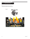
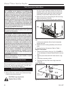
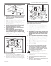
• Ensure the orange lead from the pilot assembly igniter is securely connected to the
terminal labeled “I” and the white lead from the flame rectification sensor is securely
connected to the terminal labeled “S” on the control module.
• Make sure the orange and white leads from the module are securely connected to
the terminals labeled “PILOT” on the valve body.
• Ensure the black GROUND wire is securely connected to an appropriate metal por-
tion of the valve or pilot assembly. A proper ground is essential to spark igniter
operation.
• Make certain the pilot flame is in contact with the flame rectification sensor on the
pilot assembly. This valve is equipped with a pilot flame adjustment screw. If the
pilot flame is too small it will not contact the flame rectification sensor and will not
complete the safety circuit.
• Ensure the CONTINUOUS PILOT switch on the control module is set to OFF.
• Check the handheld transmitter display for the word “PILOT” on the LCD screen. If
this is displayed, press and hold the CONTINUOUS PILOT button on the handheld
transmitter for approximately 10 seconds to turn off continuous pilot mode.
Pilot will not light/stay lit
Pilot flame is always on/ will
not extinguish