


Special offers from our partners!

Find Replacement BBQ Parts for 20,308 Models. Repair your BBQ today.

22
Chateau™ Direct Vent Gas Fireplace
20011957
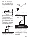
Vertical Through-the-Roof
Applications
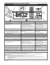
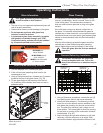
Use of Restrictor Plate
for Vertical Venting Application
The primary purpose for the vent restrictor is to regain
flame height under certain venting conditions as
outlined below.
Flue Restrictor Plate Installation
Refer to Page 17 for your venting configuration and
combination of restrictor plate requirement.
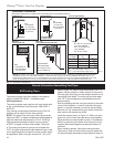
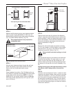
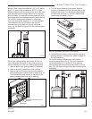
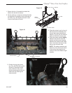
3. Install the two (2) short brackets, using sheet metal
screws, at the top right and left corners of the fire
-
place window frame. (Fig. 26) NOTE: If top corners
of the window frame do not have two (2) pre-drilled
holes, you must drill these holes per Step 4.
4. For window frames not having pre-drilled holes:
Align the short brackets so the edge of the bracket
is exactly aligned with the side edge of the fireplace
window’s top flange, as shown in Figure 27. Mark
the location of the holes using a pencil mark through
the bracket holes. Drill 1/8” holes at each of the four
(4) locations. Mount brackets using four (4) sheet
metal screws.
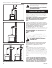
5. Set the Vista door assembly provided with your kit
in front of the glass frame assembly on the fireplace
(the outside side).
6. Have the machine screws provided with the kit within
reach.
7. Slide the Vista door assembly over the fireplace win
-
dow frame aligning the four (4) holes with the four
(4) brackets.
8. Using the machine screws, attach the Vista door to
the four (4) brackets. Do not overtighten.
WARNING: The glass frame assembly pro
-
vided with the fireplace must be left in place
for proper operation. Failure to do so could
cause property damage and malfunction of the
fireplace.
Glass
Assembly
Flange
U-Shaped Bracket
Drill Holes for Vista Door
Here
Surround Opening
Edge
Glass Assembly
Frame
Glass
KT784
Fig. 27 Vista door top hole locations.
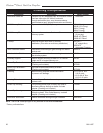
Flue Restrictor Plate Guide
Typical Applications NG LP
SK8DVSK or
2’ (610mm) vertical,
2’ (610mm) horizontal None None
4’ (1.2m) vertical, 4
¹⁄₂” flue
10’ (3m) horizontal, None restrictor
8’ (2.4m) vertical
12’ (3.7m) vertical & greater 6
³⁄₄” flue 6³⁄₄” flue
restrictor restrictor
FP1364a
restrictor plate
7/07 djt
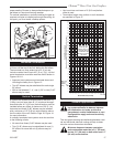
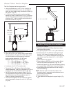
Flue Opening
Restrictor
Plate
Sheet Metal
Screws
FP1364a
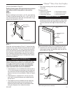
Fig. 28 Restrictor plate location.
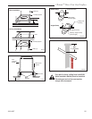
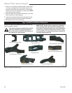
DVT38S2
Use tin snips to cut
along outer slots to
make 4¹⁄₂” (114 mm)
restrictor plate. (Refer
to Page 17)
NOTE: The joints of the inner pipe (flue pipe) must be
taped with 550°F or higher temperature metal adhesive
tape that meets the requirements of F.A.R. 25.853(a).
High temperature sealant milpack or stove cement of
550°F or higher could be used instead. The joints of The
outer pipe (fresh air pipe) must be taped with 315°F or
higher temperature metal adhesive tape or the use of
high temperature milpack or stove cement would be ap-
Restrictor Plate Installation
Using the two (2) screws provided along with the
flue restictor plate shipped with the logset, fasten the
restrictor plate to the firebox top through the front of the
unit. (Fig. 28)