


Special offers from our partners!

Find Replacement BBQ Parts for 20,308 Models. Repair your BBQ today.

17
Chateau™ Direct Vent Gas Fireplace
20011957
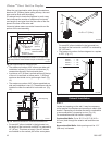
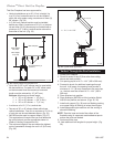
Horizontal Termination
The vent must rise vertically a minimum of 24”
(610 mm) off the top of the unit, before the first elbow.
The horizontal run may extend up to 20’ (6 m) and
include a vertical rise of up to 40’ (12 m). (Fig. 14) Hori-
zontal termination must also meet the criteria shown in
Figures 10 & 11.
• Approved vent systems must terminate above and
including the heavy line in Figure 13.
• Two 45° elbows may be substituted for each single
90° elbow.
• With a rise between 2’ - 4’, one (1) 90° or two (2) 45°
elbows may be used.
Vertical Termination
A vertical vent system must terminate no less than 12’
(3.66 m) and no more than 40’ (12 m) above the appli-
ance flue collar. A 2’ (610 mm) vertical section must be
installed before any offset. A maximum of 20’ (6.1 m)
horizontal and three (3) 90° elbows may be installed
with a minimum of 12’ (3.66 m) vertical section above
the flue collar of the unit. Refer to Page 18, Figure 14
for more information.
A vertically terminated vent system must also conform
to the following criteria:
• No more than three (3) 90° elbows may be used.
• Two (2) 45° elbows may be substituted for one (1)
90° elbow. No more than six (6) elbows may be
used.
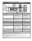
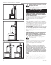
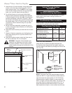
Vertical Run (in feet)
(Measured from the appliance flue collar to the top of the vent pipe.)
Horizontal Run (in feet)
• • • • •• • •• •• •
• ••• • • • • • •
• ••••• ••• •••••••••••
••• •••• •••••••••
• •• •• • •• • •
• ••• •• • ••• ••••••••••••••
May use up to
three (3) 90°
elbows, but must
not have two (2)
consecutive 90°
elbows in horizon-
tal plane
Unacceptable vent-
ing configuration
FP1359a
Fig. 13 Horizontal vent termination window.
May use
one (1)
elbow
only
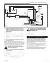
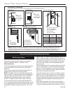
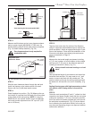
proper sealing. Be sure to always attach straps on up-
per elbow to a structural framing member.
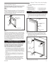
For vertical installations, continue installing the pipe as
required until pipe is installed up through the ceiling. At
this point, you must install a firestop spacer.
• Vent must rise a minimum of 2’ (610 mm) before
offset is used.
• Termination height must conform to roof clearance
as specified in Figure 37.
• • • • • • • • • • ••
• ••• • •• • • • • • • •
•• ••• •••• •• • • • • • •• • • •• • •
• •• • • • • •
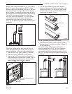
Pipe Section
Pipe
Rim
Pipe
Rim
Hem
Lance
FP1468
Fig. 12 Install pipe, listening for the snap-lock to fasten.
UP
Sidewall Applications
Since it is very important that the vent-
ing system maintain its balance between
the combustion air intake and the flue
gas exhaust, certain limitations as to vent
configurations apply and must be strictly
adhered to.
The vent graph showing the relationship between verti-
cal and horizontal side wall venting will help to deter-
mine the various dimensions allowable.
Minimum clearance between vent pipes
and combustible materials is 3¹⁄₂” (89 mm)
on top, 2¹⁄₂” (64 mm) on both sides and 1¹⁄₂”
(38 mm) on the bottom.