


Special offers from our partners!

Find Replacement BBQ Parts for 20,308 Models. Repair your BBQ today.

19
Chateau™ Direct Vent Gas Fireplace
20011957
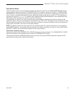
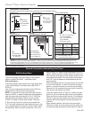
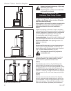
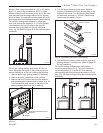
STEP 2
Measure wall thickness and cut zero clearance sleeve
parts to proper length (MAXIMUM 12”/305 mm). As-
semble sleeve using #8 sheet metal screws (supplied).
(Fig. 19) Install firestop assembly. (Fig. 34)
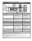
VO584-100
Vent Opening
2/99 djt
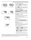
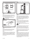
Vent Opening for Combustible Wall
16¹⁄₄”
(413mm)
Fireplace Hearth
Framing
Detail
Vent Opening for Noncombustible Wall
11¹⁄₄”
(286mm)
VO584-100
Fig. 18 Locate vent opening on wall.
16¹⁄₄”
(413mm)
ZCS101
Zero Clearance Sleeve
3/11/99 djt
Adjustable Zero
Clearance Sleeve
Max. Length
12” (305mm)
#8 Screws (2)
#8 Screws (2)
ZCS101a
Fig. 19 Adjustable zero clearance sleeve.
STEP 3
Slide the zero clearance sleeve through the wall and
install the firestop on the inside surface of the wall.
Secure with four (4) #8 sheet metal screws.
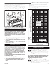
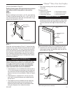
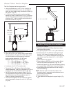
STEP 4
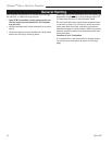
Place fireplace into position. (Fig. 20) Measure the ver-
tical height (X) required from the base of the flue collars
to the center of the wall opening. NOTE: If using the
SK8DVSK Kit, the vertical section of pipe is telescopic
and could provide adjustment from 24” up to 40” (610
mm to 1016 mm).
Zero clearance sleeve is only required for
combustible walls.
STEP 5
Tape the inner and outer flue collars of the fireplace
using UL approved metal adhesive tape to ensure the
joints are sealed. Attach an appropriate length of vent
pipe to the fireplace. Follow with the installation of the
inner and outer elbow, tape elbow joints and secure
joints as described on Page 16.
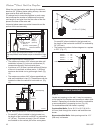
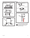
STEP 6
Measure the horizontal length requirement including
a 2” (51 mm) overlap, ie from the elbow to the outside
wall face plus 2” (51 mm) (or the distance required if
installing a second 90° elbow). (Fig. 21)
Always install horizontal venting on a level
plane.
X
FP1456
Fig. 20 Vertical height requirement.
Firestop
Zero Clear-
ance Sleeve
STEP 7
Use appropriate length of pipe sections and install the
horizontal vent sections. You may need to cut 1’ wall
section to size to be flush with the outside wall. The
sections which go through the wall are packaged with
the starter kit, and can be cut to suit if necessary. (Fig.
22)
Sealing firestop gaps with high temperature sealant
will restrict cold air being drawn in around fire-
place.
STEP 8
Guide the vent terminations 8” and 11” collars into their
respective vent pipes. Double check that the vent pipes
overlap the collars by 2” (51 mm). Secure the termina-
tion to the wall with screws provided and caulk around
the wall plate to weatherproof. (Fig. 23) As an alterna-
tive to screwing the termination directly to the wall you
may also use expanding plugs or an approved exterior
construction adhesive.