


Special offers from our partners!

Find Replacement BBQ Parts for 20,308 Models. Repair your BBQ today.

16
Chateau™ Direct Vent Gas Fireplace
20011957
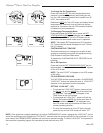
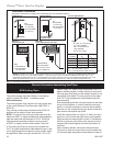
Outside Corner
Inside Corner
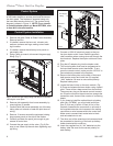
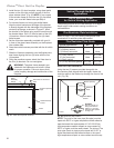
Termination Clearances
Termination clearances for buildings with combustible and noncombustible exteriors.
G =
Combustible
6" (152 mm)
Noncombustible
2" (51 mm)
F =
Combustible
6" (152 mm)
Noncombustible
2" (51 mm)
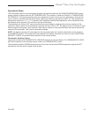
G
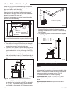
Balcony -
with no side wall
M =
Combustible &
Noncombustible
12" (305 mm)
M
Balcony -
with perpendicular side wall
M = 24" (610 mm)
P = 20” (508 mm)
M
F
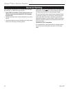
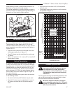
Alcove Applications*
C
D
C
E
V
V
Combustible &
Noncombustible
V
V
V
E = Min. 6” (152 mm) for
non-vinyl sidewalls
Min. 12” (305 mm) for
vinyl sidewalls
O = 8’ (2.4 m) Min.
O
P
584-15
No.
of Caps D
Min.
C
Max.
1 3’ (914 mm) 2 x D
Actual
2 6’ (1.8 m) 1 x D
Actual
3 9’ (2.7 m) 2/3 x D
Actual
4 12’ (3.7 m) 1/2 x D
Actual
D
Min.
= # of Termination caps x 3
C
Max.
= (2 / # termination caps) x D
Actual
*NOTE: Termination in an alcove space (spaces open only on one side and with an overhang) is permitted with the dimensions
specified for vinyl or non-vinyl siding and soffits. 1. There must be a 3’ (914 mm) minimum between termination caps. 2. All
mechanical air intakes within 10’ (1 m) of a termination cap must be a minimum of 3’ (914 mm) below the termination cap. 3. All
gravity air intakes within 3’ (914 mm) of a termination cap must be a minimum of 1’ (305 mm) below the termination cap.
Fig. 11 Termination clearances.
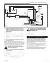
General Information Assembling Vent Pipes
SK8 Venting Pipes
Canadian Installations:
The venting system must be installed in accordance
with the current CSA-B149 .1 installation code.
USA Installations:
The venting system must conform with local codes and/
or the current National Fuel Gas code ANSI Z223.1/
NFPA 54.
Only venting components manufactured by CFM Cor-
poration can be used in Direct Vent systems.
NOTE: The joints of the inner pipe (flue pipe) must be
taped with 550°F or higher temperature metal adhesive
tape that meets the requirements of F.A.R. 25.853(a).
High temperature sealant milpack or stove cement
of 550°F or higher could be used instead. The joints
of The outer pipe (fresh air pipe) must be taped with
315°F or higher temperature metal adhesive tape or the
use of high temperature milpack or stove cement would
be applicable. When using the unitized 30°, 45° or 90°
elbows, apply 1/4” bead of high temperature, 550°F or
higher, sealant (milpack or stove cement) to the joint of
the inner pipe (flue pipe) and the straight section as it is
impossible to be taped. The outer pipe must be taped
with 315°F high temperature metal adhesive tape for
proper sealing.
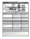
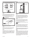
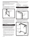
Start by attaching the first vent pipe section to the collar
on top of the fireplace. In order to attach the first pipe
section, it may be necessary to remove the top shield.
Remove four (4) screws securing top shield, install first
pipe section and replace top shield.
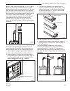
Install the pipe as shown in Figure 12. When you get a
good lock, you will hear the pipe clearly snap together.
Once sections are snap-locked in place, it is extremely
difficult to get them apart. Make sure the pipe is firmly
snapped and locked together as each pipe section is
mounted.
When installing elbows, follow the same procedure.
The joints of inner and outer elbow must be taped with
UL approved high temperature metal adhesive tape for