


Special offers from our partners!

Find Replacement BBQ Parts for 20,308 Models. Repair your BBQ today.

18
Chateau™ Direct Vent Gas Fireplace
20011957
When the vent termination exits through foundations
less than 20” (508mm) below siding outcrop, the vent
pipe must be flush with the siding.
It is always best to locate the fireplace in such a way
that minimizes the number of offsets and horizontal
vent length of vent pipe from the flue collar of the fire
-
place to the face of the outer wall.
Horizontal plane means no vertical rise exists on this
portion of the vent assembly.
FP1453
DVT38s2
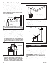
Top vent max run
3/17/04 djt
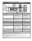
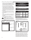
NOTE: Apply high temperature sealant or UL approved
high temperature metal adhesive tape as directed on Page
16.
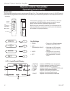
14’ (4.3m)
Pipe Straps
Every 3’
(914mm)
Firestop/Zero
Clearance Sleeve
Pipe
Straps
Every 3’
(914mm)
20’ (6m)
FP1453
Fig. 14 Support straps for horizontal runs.
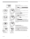
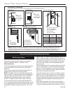
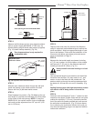
Minimum 2’
(610mm) Section
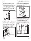
Unitized Elbow
(SK890)
• The maximum number of 90° elbows per side wall
installation is three (3), but must not have two (2)
consecutive elbows in the horizontal plane.
• A minimum of 2’ (610mm) vertical section off the top
of the unit is required, an elbow and a 1’ (305mm)
maximum horizontal run to get through a wall. (Fig.
15)
• The maximum number of 45° elbows permitted per
side wall installation is two (2). These elbows can be
installed in either the vertical or horizontal run. (Fig.
15)
3'
(914mm)
FP1454
DVT38s2
horizontal plane
3/17/04 djt
2'
(610mm)
6'9"
(2080mm)
C
L
FP1454
Fig. 15 Minimum vertical run / maximum horizontal run.
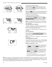
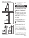
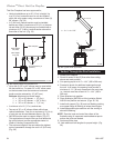
Wall Opening
10'
(3m)
A
A + B = 17' (5.2m)
B
FP1238b
Fig. 16 Maximum vent run with elbows.
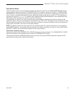
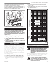
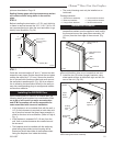
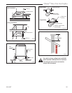
Example:
Elbow 1 = 90°
Elbow 2 = 45°
Elbow 3 = 45°
Elbow 4 = 90°
Total angular variation = 270°
FP1455
Fig. 17 Maximum number of elbow degrees.
1
2
4
• • •••• ••••••
• •••• ••••• •••• •• • • • • • • • • • • • • • • • •
••••••••••
• • • •••••••••••
••• •••••••••••••••••••••
3
STEP 1
Locate vent opening on the wall. It may be necessary
to first position the fireplace and measure to obtain hole
location. Depending on whether the wall is combustible
or noncombustible, cut opening to size. (Fig. 18)
For combustible walls first frame in opening.
Combustible Walls: Cut a 16¹⁄₄”H x 16¹⁄₄” W (413 x
413 mm) hole through the exterior wall and frame as
shown.
Noncombustible Walls: Hole opening must be 11
¹⁄₄”
(286 mm) in diameter.
Sidewall Installation
• For each 45° elbow installed in the horizontal run,
the length of the horizontal run MUST be reduced by
18” (45 cm). This does not apply if the 45° elbows
are installed on the vertical part of the vent system.
For each 90° elbow installed in the horizontal run,
the length of the horizontal run MUST be reduced by
36” (914 mm).
• The maximum number of elbow degrees in a system
is 270°. (Fig. 17)