


Special offers from our partners!

Find Replacement BBQ Parts for 20,308 Models. Repair your BBQ today.

27
Chateau™ Direct Vent Gas Fireplace
20011957
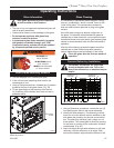
Only glass approved by CFM Corporation
should be used on this fireplace.
1. Turn the fireplace OFF (including the pilot).
2. If the unit has been operating allow time for the
components to cool.
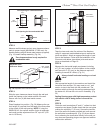
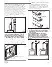
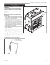
3. Using a Phillips screwdriver, unfasten two (2) screws
located at the top of the glass frame. (Fig. 39)
4. Tilt the glass frame at the top away from the unit.
Lift it carefully off the bottom door track and set on
padded surface.
It is necessary to periodically clean the glass. During
start-up, condensation, which is normal, forms on the
inside of the glass. This condensation causes lint,
dust and other airborne particles to cling to the glass
surface.
Also initial paint curing may deposit a slight film on
the glass. It is therefore recommended the glass be
cleaned two or three times with a non-ammonia based
household cleaner and warm water (gas fireplace glass
cleaner is recommended) within the first few weeks of
operation.
After the initial cleaning process the glass should be
cleaned two or three times during each operating
season depending on the environment in the house.
Clean the glass after the first two weeks of
operation.
• The use of any non-approved replacement glass will
void all product warranties.
• Care must be taken to avoid breakage of the glass.
• Do not operate appliance with glass front
removed, cracked or broken.
• A replacement glass frame assembly (complete
with gasket) is available through your CFM
Corporation dealer and should only be installed
by a licensed qualified service person.
Operating Instructions
Glass Information
Glass Frame Assembly Removal
Glass Cleaning
Ceramic Refractory Installation
The ceramic refractories are fragile and
should be handled with care. Due to the
size of the refractories, an assistant may be
helpful.
�
FP1800
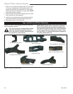
Phillips
Screws
Fig. 39 Remove Phillips screws, tilt frame forward and lift off
bottom door track.
FP1580a
DVT38s2
refractory
6/05
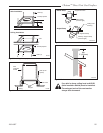
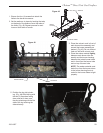
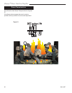
Refractory,
Left Side
Refractory,
Right Side
FP1580a
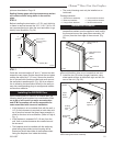
Fig. 40 Ceramic refractory panels.
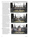
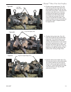
1. Using a Robertson screwdriver, remove the two (2)
nuts holding each fettle to the burner assembly.
2. Identify the side refractory. The refractory with the
small cut out at the bottom must be installed on the
side where the plumbing for the pilot and manifold
are. The other side refractory has a larger cut out
at the bottom. This is designed to allow the opening
for the fresh air coming to the combustion chamber
unobstructed. (Fig. 40)
3. Start with either the right side refractory or left side
refractory. Hold the refractory at an angle. Slide
and seat the bottom edge toward the bottom of the