


Special offers from our partners!

Find Replacement BBQ Parts for 20,308 Models. Repair your BBQ today.

23
Chateau™ Direct Vent Gas Fireplace
20011957
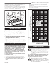
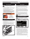
plicable. When using the unitized 30°, 45° or 90° elbows,
apply 1/4” bead of high temperature, 550°F or higher,
sealant (milpack or stove cement) to the joint of the inner
pipe (flue pipe) and the straight section as it is impossi-
ble to be taped. The outer pipe must be taped with 315°F
high temperature metal adhesive tape for proper sealing.
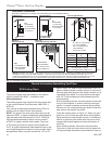
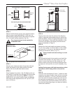
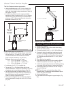
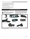
For vertically venting either propane or natural gas
units, with vertical vent heights of 12’ (3.7m) or greater,
(measured from the top of the flue collar) the flue
restrictor plate as supplied with this unit should be
used. (Fig. 29) Refer to Figure 28 for flue restrictor plate
installation.
X
FP1461
Fig. 29 Flue restrictor plate use in straight up installation.
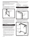
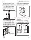
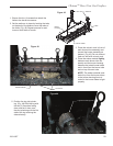
Rectangular Restrictor Plate
Deflector
Screws
FP1615
Fig. 30 Turn rectangular restrictor plate over to partially cover
opening.
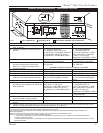
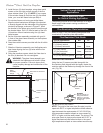
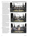
4. Turn the burner housing upside down. Remove
the two (2) screws securing the shutter plate to the
bottom of the burner. Turn the shutter plate around
so the bottom opening is 1” (25 mm). Replace the
screws removed earlier. (Fig. 31)
1“ (25 mm)
FP1616
shutter plate
4/06
Remove Screws
Shutter
Plate
Shutter Plate
FP1616a
Fig. 31 Turn shutter plate over to cover opening.
5. Reinstall burner housing, fettle, andirons, logs and
glowing embers in reverse order. (Refer to Page 28
for log installation)
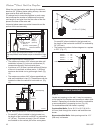
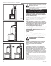
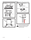
For vertical venting configurations that include a
minimum vertical rise of 12’ (3.7 m) and a maximum
horizontal offset of 10’ (3 m) the 4
¹⁄₂” flue restrictor
plate supplied with this unit should be used on LP unit
only. (Fig. 32) Refer to Figure 28 for flue restrictor plate
installation.
For LP gas venting straight vertical with 20’ (6 m) or
more, adjust the primary air to the burner housing as
well as the fresh air to the unit by doing the following:
1. Remove glass, logs, glowing embers (if installed).
2. Remove andirons, fettles and burner housing.
3. Remove the two (2) screws securing the deflector
and the rectangular restrictor plate in place. (Fig. 30)
Turn the restrictor plate around so the body of the
plate will extend down over the air opening.
FP1462
Fig. 32 Restrictor plate use with horizontal offset.