


Special offers from our partners!

Find Replacement BBQ Parts for 20,308 Models. Repair your BBQ today.
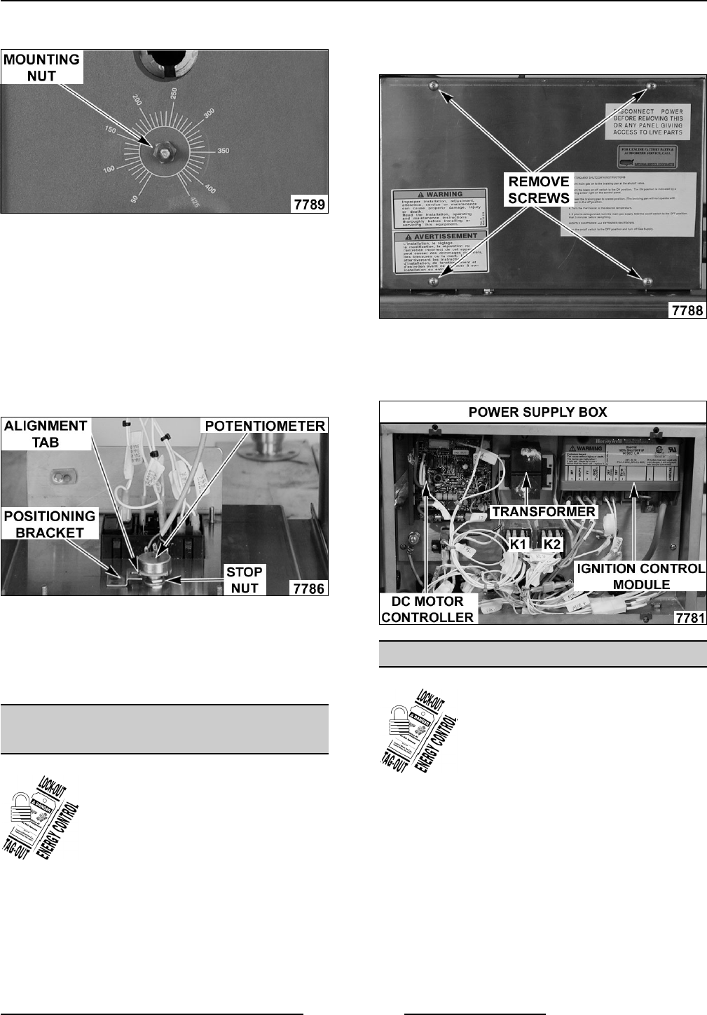
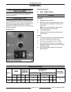
GAS BRAISING PANS - REMOVAL AND REPLACEMENT OF PARTS
F25121 (February 2003)
Page 5 of 32
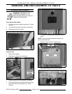
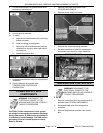
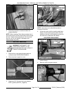
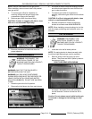
8. Pull temperature dial from potentiometer shaft
and remove mounting nut.
9. Control panel is removed.
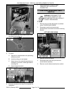
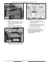
10. To install.
A. Align tab on potentiometer with positioning
bracket on panel.
B. Install mounting nut and tighten.
C. Adjust stop nut on potentiometer body (as
necessary) to ensure a water tight seal on
mounting nut.
D. Attach temperature dial.
11. Reverse procedure from step 6 to complete the
installation.
12. Check calibration as outlined under
TEMPERATURE CONTROLLER
CALIBRATION.
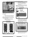
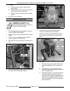
POWER SUPPLY BOX
COMPONENTS
WARNING: DISCONNECT THE
ELECTRICAL POWER TO THE
MACHINE AND FOLLOW LOCKOUT /
TAGOUT PROCEDURES.
CAUTION: Certain components in this system
are subject to damage by electrostatic discharge
during field repairs. A field service grounding kit
is available to prevent damage. The field service
grounding kit must be used anytime a control
board is handled.
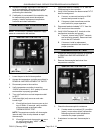
1. Remove front panel as outlined under
COVERS AND PANELS.
2. Remove power supply box cover.
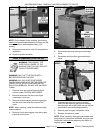
3. Remove the component being replaced.
4. Reverse procedure to install the replacement
component then check for proper operation.
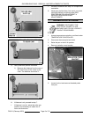
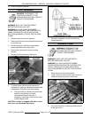
TEMPERATURE CONTROLLER
WARNING: DISCONNECT THE
ELECTRICAL POWER TO THE
MACHINE AND FOLLOW LOCKOUT /
TAGOUT PROCEDURES.
1. Remove control box from the control panel as
outlined under COVERS AND PANELS.
2. Disconnect lead wires from temperature
controller.
3. Remove temperature controller from control
box.