


Special offers from our partners!

Find Replacement BBQ Parts for 20,308 Models. Repair your BBQ today.
GAS BRAISING PANS - REMOVAL AND REPLACEMENT OF PARTS
F25121 (February 2003)
Page 11 of 32
NOTE: On the bottom lift arm bushing, the bushing
head must
be positioned between the lift arm and the
crank assembly to create approximately 1/32"
spacing.
9. Reverse procedure from step 5 to complete the
installation.
10. Check for proper operation.
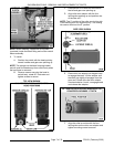
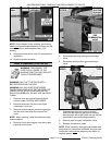
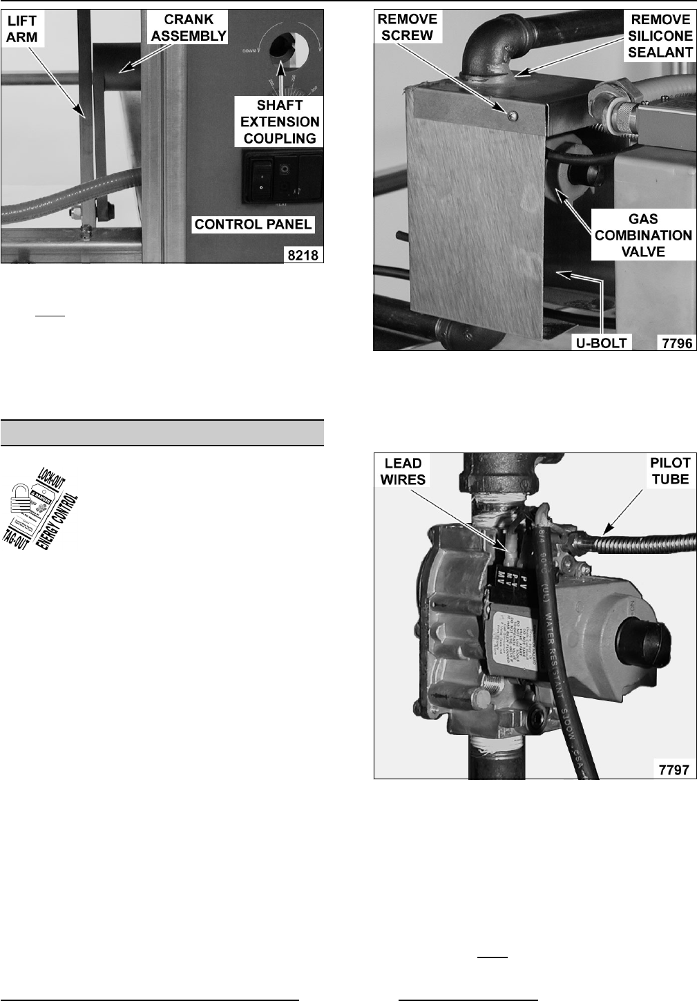
GAS COMBINATION VALVE
WARNING: DISCONNECT THE
ELECTRICAL POWER TO THE
MACHINE AND FOLLOW LOCKOUT /
TAGOUT PROCEDURES.
WARNING: SHUT OFF THE GAS SUPPLY
BEFORE SERVICING THE UNIT.
WARNING: ALL GAS JOINTS DISTURBED
DURING SERVICING MUST BE CHECKED FOR
LEAKS. CHECK WITH A SOAP AND WATER
SOLUTION (BUBBLES). DO NOT USE AN OPEN
FLAME.
1. Remove front, rear and left side panels as
outlined under COVERS AND PANELS.
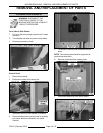
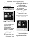
2. Remove screw from the top cover of gas
combination valve box.
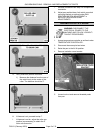
3. Remove silicone sealant around the gas pipe
and the slot in top cover then remove the
cover.
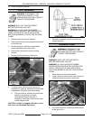
NOTE: When installing, clean the areas and apply
silicone sealant.
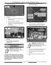
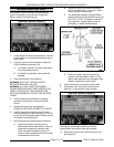
4. Remove U-bolt securing gas valve box to gas
pipe then remove box.
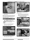
5. Disconnect lead wires from gas combination
valve.
6. Disconnect pilot tube from gas combination
valve.
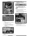
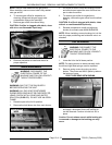
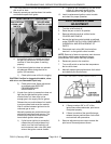
7. Separate gas pipe union (near manifold),
remove U-bolt securing gas pipe to braising
pan frame (at rear of pan) then remove the gas
combination valve and piping assembly.
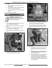
8. Remove pipe from gas combination valve.
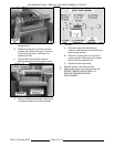
9. Reverse procedure to install.
NOTE: When installing, clean gas pipe threads and
apply pipe joint compound to threads. Any pipe joint
compound used must
be resistant to the action of
propane gases.