


Special offers from our partners!

Find Replacement BBQ Parts for 20,308 Models. Repair your BBQ today.

GAS BRAISING PANS - ELECTRICAL OPERATION
F25121 (February 2003) Page 28 of 32
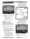
SEQUENCE OF OPERATION
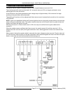
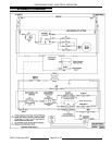
Refer to schematic diagram AI1341 for the electrical
sequence of operation. Manual pan lift is the
standard configuration.
Heating
1. Conditions.
A. 120VAC to braising pan, polarity is correct,
and is properly grounded.
1) Temperature controller energized.
2) 24VAC transformer energized.
B. Temperature dial at lowest setting
(potentiometer fully CCW).
NOTE: Temperature controller internal relay
"HEAT" contacts remain open (N.O.).
C. Pan temperature is below 200/F.
D. On/off switch off.
E. Pan position/down limit switch N.O.
contacts closed (pan down).
F. Gas supply on.
G. Gas combination control valve on.
2. Turn on/off switch on.
A. Indicator light (amber) comes on.
3. Set the temperature dial to call for heat.
A. Internal relay on temperature controller is
energized and the "HEAT" contacts close
(N.O.).
1) Heat light (red) comes on.
2) Ignition control module.
NOTE: If pan is raised 2.25" to 2.50" at the rear,
pan position/down limit switch N.O. contacts will
open and de-energize the heating circuit.
4. Refer to IGNITION CONTROL MODULE.
5. Braising pan reaches set point temperature.
A. Internal relay on temperature controller is
de-energized and the "HEAT" contacts
open (N.O.).
1) Heat light (red) goes out.
2) Power is removed from the ignition
control module.
6. Braising pan will continue to cycle with the
temperature controller until the pan is raised or
the on/off switch is turned off.
Motorized Pan Lift (Option)
Refer to the dashed line sections labeled
"MOTORIZED LIFT OPTION" on the schematic
diagram for the integration of the motorized pan lift
components into the sequence of operation.
1. Conditions.
A. 120VAC to braising pan, polarity is correct,
and is properly grounded.
B. 24VAC transformer energized.
C. On/off switch off.
D. Lift control switch off (center position).
E. Lid switch N.O. contacts closed (lid
opened).
F. Up limit switch N.C. contacts closed (pan
position is less than full tilt).
G. Pan position/down limit switch N.O.
contacts closed; and
N.C. contacts open
(pan down).
NOTE: The pan position/down limit
switch are
contained in the same switch body. Both sets of
DPST contacts are utilized.
2. Turn on/off switch on.
A. Indicator light (amber) comes on.
NOTE: If the temperature dial is set to call for
heat, the ignition trial starts and module begins
sparking.
3. Operate the lift control switch to raise the pan
(momentary on - raise).
A. K1 relay coil is energized thru the up limit
switch N.C contacts.
1) K1 4/7 N.O. contacts close.
2) K1 9/6 N.O. contacts close.
3) K1 8/5 N.O. contacts close.
B. 120VAC to DC motor controller thru K1 4/7
N.O. contacts.
1) 90VDC output is activated at terminals
A + (positive) and A - (negative). DC
lift motor powered thru K1 9/6 N.O.
contacts, K1 8/5 N.O. contacts and
pan raises.
4. When the pan is raised 2.25" to 2.50" at the
rear, pan position/down limit switch contacts
change state. The N.O contacts open to remove
power from the heating circuit; and the N.C
contacts close. Power is then available for K2
relay coil thru the N.C. set of contacts.
The pan can still be raised or lowered thru its
travel range by operating the lift control switch.
Release switch to stop pan travel.