


Special offers from our partners!

Find Replacement BBQ Parts for 20,308 Models. Repair your BBQ today.
GAS BRAISING PANS - SERVICE PROCEDURES AND ADJUSTMENTS
F25121 (February 2003)
Page 15 of 32
SERVICE PROCEDURES AND ADJUSTMENTS
WARNING: CERTAIN PROCEDURES IN THIS SECTION REQUIRE ELECTRICAL TEST OR MEASUREMENTS
WHILE POWER IS APPLIED TO THE MACHINE. EXERCISE EXTREME CAUTION AT ALL TIMES. IF TEST
POINTS ARE NOT EASILY ACCESSIBLE, DISCONNECT POWER AND FOLLOW LOCKOUT / TAGOUT
PROCEDURES, ATTACH TEST EQUIPMENT AND REAPPLY POWER TO TEST.
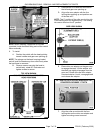
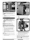
TEMPERATURE CONTROLLER
CALIBRATION
NOTE: Verify condition of thermocouple as outlined
under THERMOCOUPLE TEST before proceeding.
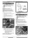
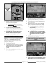
1. At the geometric center on the pan cooking
surface, clean an area approximately 3" inches
in diameter.
2. Apply a thin layer of fresh cooking oil to the
cleaned area and place a temperature sensing
disk on the pan cooking surface.
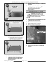
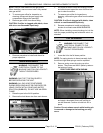
3. Turn on/off switch on and set temperature dial
to 250°F.
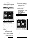
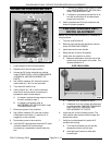
4. Monitor the heat light (red) on the control panel.
When temperature controller is calling for heat,
light will be on. If temperature controller is
satisfied, light will be off.
A. Allow the temperature controller to cycle
three times to stabilize the pan
temperature.
B. Record the temperature when the
temperature controller cycles off and on for
the next three cycles.
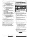
5. Calculate the differential by subtracting the
temperature indicated when heat light goes out
from temperature indicated when heat light
comes on.
A. The differential calculated should be less
than 20°F.
1) If the differential is less
than 20°F,
temperature controller is functioning
properly.
a. Proceed to average temperature.
2) If the differential is more
than 20°F,
the temperature controller is
malfunctioning.
a. Install a replacement
temperature controller and check
calibration.
6. Calculate the average temperature by adding
the temperature indicated when the heat lamp
goes out to the temperature indicated when the
heat lamp comes on & divide this answer by 2.
A. If the average temperature is less
than
10°F of the dial setting, temperature
controller is properly calibrated.
B. If the average temperature is more
than
10°F of the dial setting, temperature
controller calibration must
be adjusted.
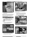
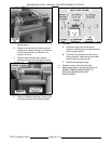
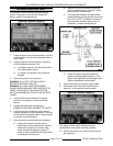
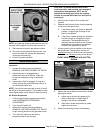
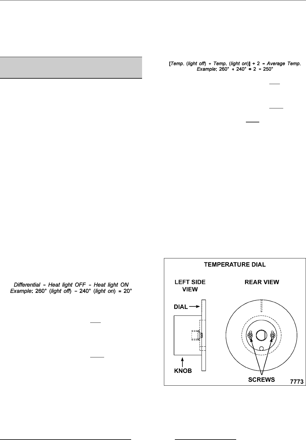
7. Using the temperature scale on the overlay as a
guide, align the edge on a short piece of tape to
the temperature calculated in step 6 and apply
tape to knob as a reference point.
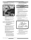
8. Remove temperature dial from shaft.
9. Loosen screws on the back of dial.
A. Hold the knob and rotate dial to the edge of
the tape used for reference. This
adjustment offsets the indicated
temperature on the dial to the actual
temperature measured.
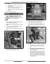
NOTE: With knob facing user, a clockwise
rotation increases temperature and a counter-
clockwise rotation decrease temperature.
B. Hold the dial & knob together to maintain
the adjusted setting and tighten screws.
10. Replace temperature dial on shaft.
11. Turn the temperature dial to the lowest setting
then back to 250°F.