Special offers from our partners!

Find Replacement BBQ Parts for 20,308 Models. Repair your BBQ today.
GAS BRAISING PANS - SERVICE PROCEDURES AND ADJUSTMENTS
F25121 (February 2003)
Page 19 of 32
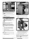
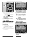
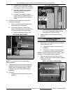
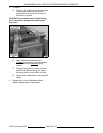
10. Manually operate pan position/down limit switch
and observe pilot burner flame.
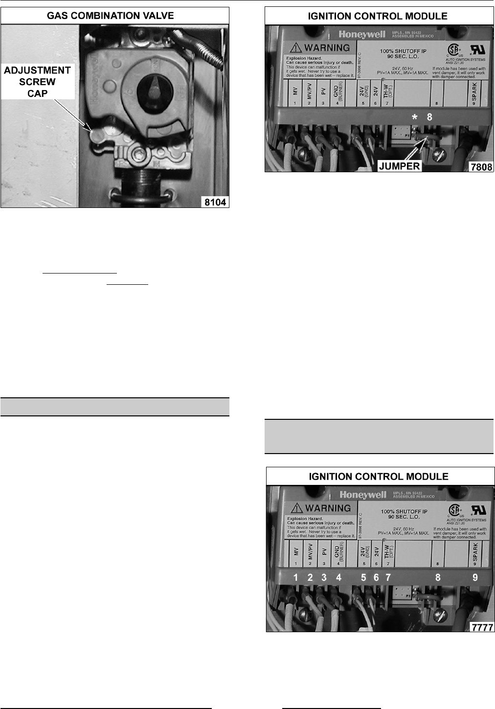
A. To increase pilot flame, turn the screw
counterclockwise. To decrease pilot flame,
turn the screw clockwise
.
11. Once the pilot flame
has been adjusted
correctly, release the pan position
/down limit
switch, turn the on/off switch off and replace the
adjustment screw cap.
12. Re-connect main valve (MV) lead wire from
terminal 1 on the ignition control module.
13. Lower the pan to the full down position and
check for proper operation.
FLAME SENSE CURRENT TEST
NOTE: You must complete the SPARK IGNITION
TEST prior to checking flame sense current.
If pilot burner lights but will not maintain flame,
perform the following test.
1. Turn the on/off switch off.
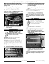
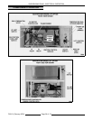
2. Access the ignition control module as outlined
under POWER SUPPLY BOX COMPONENTS
IN REMOVAL AND REPLACEMENT OF
PARTS.
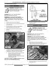
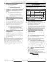
3. Remove jumper wire between terminals marked
with an asterisk (*) & 8.
4. Set VOM to micro amp scale (DC) and connect
the black meter lead (-) to the asterisk (*)
terminal and red meter lead (+) to terminal 8.
5. Turn on/off switch on and set the temperature
dial to call for heat.
6. With pilot burner lit, meter reading should be
above 1.0 micro amp (minimum) and steady.
A. If reading is greater than or equal to 1.0
micro amp then flame sense current is
within tolerance.
1) Turn on/off switch off and replace
jumper wire.
B. If reading is less than 1.0 micro amp and
the condition of the ignitor/flame sense has
been verified as good, turn on/off switch
off.
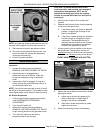
7. Install a replacement ignition control module
and check for proper operation.
IGNITION CONTROL MODULE
TEST
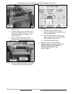
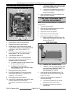
1. Lower the pan to the full down position, turn the
on/off switch on and set the temperature dial to
call for heat.


