


Special offers from our partners!

Find Replacement BBQ Parts for 20,308 Models. Repair your BBQ today.

GAS BRAISING PANS - ELECTRICAL OPERATION
F25121 (February 2003)
Page 25 of 32
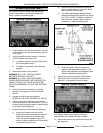
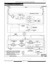
ELECTRICAL OPERATION
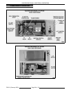
COMPONENT FUNCTION
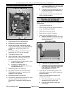
BRAISING PAN CONTROLS
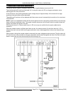
Temperature Controller .... Monitors thermocouple input (type E) and regulates braising pan temperature. An
external set point potentiometer is used for temperature adjustments.
Transformer ............. Supplies 24VAC for heating circuit. If motorized pan lift option is installed,
supplies 24VAC for lift control circuit.
ON/OFF Switch .......... Controls 24VAC to the gas heating circuit. If motorized pan lift option is installed,
controls power to lift circuit.
Power On Light (Amber) . . . Indicates on/off switch is turned on.
Heat Light (Red) .......... Indicates temperature controller is calling for heat and pan is down.
Pan Position/
Down Limit Switch ........ N.O. contacts function as pan position switch to power the gas heating circuit
when pan is down. Removes power from gas heating circuit when pan is raised.
The N.C. contacts are used for the down limit switch (motorized lift option only).
Ignition Control Module . . . Controls and monitors gas heating. Energizes pilot valve coil to supply gas to
pilot, generates spark to light gas at the pilot, monitors the presence of flame and
energizes the main valve coil upon a call for heat.
Ignitor/Flame Sense
Electrode ................ Ignites pilot burner and senses the presence of a flame. The Igniter/Flame Sense
is a component of the pilot burner.
Gas Combination
Valve ................... Allows gas flow to the pilot burner when pilot valve coil is energized; and gas flow
to the runner tube & main burners when main valve coil is energized. Also,
regulates gas manifold pressure.
MOTORIZED PAN LIFT OPTION CONTROLS
DC Motor Controller ....... Controls DC lift motor operation for raising & lowering of the pan, and provides
motor acceleration control each time the controller is powered. The controller
outputs approximately 90VDC to power the motor.
DC Lift Motor ............. Operates gear reducer to raise or lower the pan. When the correct voltage
polarity is applied thru K1 contacts, motor rotates CW to raise pan. When reverse
voltage polarity is applied thru K2 contacts, motor rotates CCW to lower the pan.
Lid Switch ............... Supplies 24VAC power to lift control switch. Used to ensure lid is open before pan
can be raised.
Lift Control Switch
(Momentary On/Off/On) .... Energizes K1 relay coil thru up limit switch contacts (N.C.) to raise the pan.
Energizes K2 relay coil thru down limit switch contacts (N.C.) to lower the pan.
The switch positions are: Center neutral (starting) position off; Momentary on -
lower pan; Momentary on - raise pan.
Up Limit Switch .......... Removes power from K1 relay coil when pan reaches full tilt (pan travel stops).
Pan Position/
Down Limit Switch ........ N.C. contacts function as down limit switch to remove power from K2 relay coil
when pan is lowered to the down position (pan travel stops). The N.O. contacts
are used for the pan position switch.
K1 "Up" Relay (3PDT) ..... Supplies power to motorized lift circuit to raise the pan when 24VAC coil is
energized.
K2 "Down" Relay (3PDT) . . . Supplies power to motorized lift circuit to lower the pan when 24VAC coil is
energized by the lift control switch. The voltage polarity to the DC motor is
reversed thru K2 contacts to turn motor CCW and lower the pan.