


Special offers from our partners!

Find Replacement BBQ Parts for 20,308 Models. Repair your BBQ today.

33
Radiance Direct Vent Gas Heater
20012697
Auto Mode
In the AUTO mode, the room temperature, set tem-
perature, flame and fan levels will be shown. AUTO will
appear next to both the flame and fan icons.
When the control is in the AUTO mode, the main burner
will turn on/off or modulate based on the heat needed
to maintain the set temperature. The flame level will
change automatically to optimize the heat output
needed to maintain the set temperature. To change the
set temperature, press the up or down key. Pushing a
key once will change the temperature by one degree.
In the AUTO mode, the fan speed will increase with
increasing flame height or decrease with decreasing
flame height. “AUTO” is displayed next to the flame and
fan icons.
Fan Override During Auto Mode
If a lower or higher fan speed is desired when operating
in the AUTO mode, the fan speed can be overridden by
pushing the fan button followed by the up or down key.
Pushing a key once will change the fan level by one
unit. In this mode “AUTO” is displayed next to the flame
icon and “MANUAL” is displayed next to the fan icon.
Change Between F/C Temperature Units
Push the up and down arrow keys simultaneously for
at least 3 seconds to toggle between Fahrenheit and
Celsius units.
Disable Thermostat Function
To disable the thermostat function in the AUTO mode,
push the time and down keys simultaneously for at
least 3 seconds.
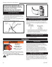
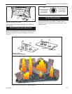
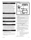
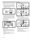
To Change Batteries
1. Remove cover on the backside of the transmitter.
Install 3 AAA batteries as shown and reattach cover.
2. Once steps 1-3 in OPERATION are completed,
receiver/valve and transmitter are now ready. Press
any button on transmitter for recognition process to
occur between the receiver/valve and transmitter.
3. Use functions as described in TRANSMITTER sec-
tion.
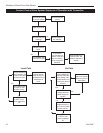
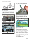
Troubleshooting
1. Locate LED light on valve.
2. LED will blink after every valid command received by
the transmitter; this is not an error.
3. Failure codes may occur anytime after pilot burner is
lit.
4. Sequence is failure code followed by light not blink-
ing for 30 seconds.
5. In the event of multiple failure codes, next failure
code follows previous failure code by approximately
3 seconds.
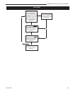
If an Error Code 3 is observed while performing the
testing, complete the following:
1. Make sure the spade connectors are pushed all the
way on. If rhe Error Code 3 is still showing, then go
to the next step.
2. Switch the front two thermopile leads with the back
two. Be sure the white lead is connected to the
spade with the white dot next to it. If the Error Code
3 is still showing, replace the thermopiles.
If an Error Code 8 is observed while performing the
testing, complete the following:
1. Confirm the valve is not in REMOTE mode.
• If the valve is producing Error Code 8 and in RE
-
MOTE mode, the valve is defective and should be
replaced.
• If the valve is in LOCAL mode and producing Error
Code 8, then go to the next step.
2. Slide the Remote/Local switch to REMOTE and
teach the valve a transmitter. The Error Code will
clear itself after approximately 1.5 minutes and re-
turn to normal operation.
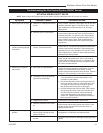
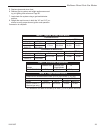
LED Count Service Action
8 Replace valve
7 Confirm stepper motor connection exists
5 Confirm fan connection exists and works
4 Confirm gas type; jumper in place
3 Replace thermopiles
2 Turn fan ON
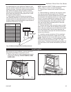
NOTE: Some keys are not active.
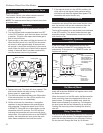
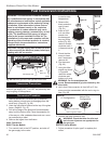
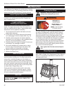
FAN
Antenna
Red
White
Red
White
FP1038
comfort valve
wiring diagram
3/24/00 djt
Comfort Control Valve
(Bottom View)
Blower
Pilot As
-
sembly
FP1038
Fig. 59 Comfort Valve wiring diagram.
White Dots