


Special offers from our partners!

Find Replacement BBQ Parts for 20,308 Models. Repair your BBQ today.

2222
Radiance Direct Vent Gas Heater
20012697
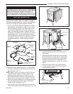
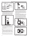
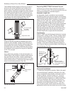
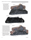
The Cathedral Ceiling Support (CCS) may be used in
pitched or flat ceiling installations and comes with a
support collar and a decorative two part square trim
plate. Install by inserting the support box down through
the framed joist opening (end with round hole first) in
the ceiling using tin snips, cut the corners of the open
end of the box such that the sides can be folded down
over the top of the joist framing members. Nail the
folded sides to the top of the framing. (Fig. 37)
Two Part Square
Trim Plate
Support Box
Support Box Collar
ST926
Fig. 37 Support box.
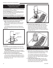
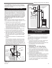
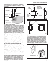
Nail to top of
framing
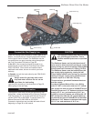
Offset Support
Strap
Offset Support
Collar
ST927
Fig. 38 Offset support.
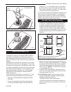
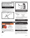
Firestop (FS)
Placed on Top
of Framed
Opening
Attic Framing
(No floor)
Maintain at Least
Minimum Clearance to
Combustibles, Wire and
Insulation
ST928
Fig. 39 Firestop spacer.
A two-part square trim plate is provided to give a fin-
ished look once installed. Simply fit the two halves of
the trim plate around the cathedral ceiling support box
hanging below the ceiling (overlapping if necessary)
and screw them to the ceiling. Both the ceiling support
and cathedral ceiling support can support a maximum
of 40’ (12 m) of pipe.
Offsets:
If any offsets are necessary in the vertical system, an
Offset Support (OS) should be installed directly above
the upper elbow of the offset. Install by attaching the
offset support band to the pipe with two #8 x 1/4” sheet
metal screws (minimum ) and secure the offset support
straps to surrounding structure. (Fig. 38)
Supporting DIRECT-TEMP: Horizontal Support
Horizontal runs of Direct-Temp should be supported
every 4’ (122 cm) of pipe. This can be done with the use
of plumbers strapping or the offset support.
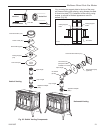
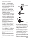
Adjustable Length (AJ)
An Adjustable Length is available to accommodate
installations where non-standard lengths are necessary.
The adjustable length telescopes down over a standard
length of pipe and provides an extension range of 3¹⁄₂”
(89 mm) to 10¹⁄₂” (267 mm). Install by sliding the inlet
end of the adjustable length over the outlet end of a
standard length of pipe. After positioning the adjustable
length appropriately, secure it to the standard length
with two (2) #8 x1/4” sheet metal screws (provided).
Seal the area between both the top and bottom of the
adjustable length outer wall and the outer wall of the
standard length with an approved silicone sealant.
Fire Stopping
DIRECT-TEMP must be firestopped wherever it passes
through floors, ceiling or walls. The only location where
a firestop is not required is at the roof level. Both verti
-
cal support components with trim plates provide for
firestopping. The wall thimble also acts as a firestop.
AT other locations, a firestop spacer (FS) should be
installed. In the attic the firestop should be placed on
top of the joist framing to prevent debris from falling into
the joist framing. (Fig. 39)
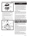
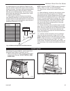
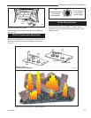
Horizontal Installation
1. Determine the appliance location. Refer to the appli-
ance manufacturer’s installation instructions for clear-
ance to combustible requirements, termination options,
number of elbows, maximum length, etc. Then posi-
tion the appliance and plan vent routing accordingly.
Consider locating the appliance in a place where there
will be no interference with wall studs, electrical wir-
ing, conduit, plumbing pipe or other obstructions. The
termination should be located at least 12” (305 mm)
(Fig. 40) above grade, remain above the snow line in
geographical areas that accumulate snow and be away