


Special offers from our partners!

Find Replacement BBQ Parts for 20,308 Models. Repair your BBQ today.

1616
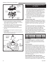
Radiance Direct Vent Gas Heater
20012697
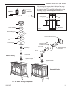
Venting System Assembly
General Information
The Radiance is approved for installation only with the
vent components listed on Pages 12 and 13. Follow the
vent component instructions exactly.
For U.S. installations: The venting system must con-
form with local codes and/or the current National Fuel
Gas Code, ANSI Z223.1/NFPA 54.
For Canadian installations: The venting system must
conform to the current CSA B149.1 installation code.
Install the Vent Adapter Pipe
(CFM Corporation Vent Components)
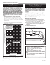
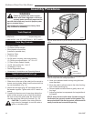
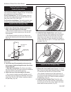
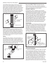
1. Attach Inner Starter Pipe, (found in the Parts
Bag), to the next section of inner pipe.
• Run a bead of sealant about 1/2” from the upper
end of the Inner starter pipe and join the two sec-
tions together.
• Drill three pilot holes into the Inner Starter and
secure the assembly with three sheet metal screws.
(Fig. 19)
CEMENT
ST211
attach inner pipe
to next section
12/4/99 djt
First Section of
Vent Pipe
1/4”-20 x 1/2”
Phillips Screw
4” Inner
Starter
Pipe
ST211
Fig. 19 Connect the inner starter with the next section of in-
ner vent pipe.
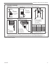
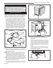
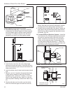
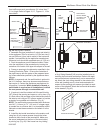
4. Install the Outer Adapter Pipe. Insert the pipe
over the stove flue collar, keeping the vertical seam
oriented to the back of the stove. Also, be sure to
align holes on the pipe with the holes on the flue
collar of the firebox. Fasten the pipe to the holes in
the flue collar with the #12 x 1/2” sheet metal screws
provided. (Fig. 21)
2. Dry fit the Inner Pipe assembly to the stove for
the purpose of determining the center line of the
pipe on the wall.
• Side Wall Terminations: Dry fit the outer elbow
with the vertical outer vent and confirm the centerline
alignment with the wall thimble opening.
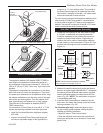
3. Attach the Inner Vent Assembly to the stove.
• Run a bead of sealant around the bottom end of
the starter pipe and attach the assembly to the stove
using three 1/4-20 x 3/8” Phillips screws provided in
the parts bag. (Fig. 20)
Fig. 20 Attach inner assembly to flue collar.
ST647
attach inner assy
4/20/01 djt
CEMENT
ST648a
Fig. 21 Fasten outer pipe with #12 x 1/2” sheet metal screw.
ST650
install outer adpater
4/20/01 djt
ST650
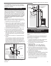
Install the Vent Adapter Pipe
(Simpson Dura-Vent Components)
1. Discard the inner starter pipe
shipped in the Parts
Bag. Using the starter pipe assembly listed on Page
12, slide the inner section out to allow access.
• Run a bead of sealant around the bottom end of
the starter pipe and attach the assembly to the stove
using three 1/4-20 x 3/8” Phillips screws provided in
the parts bag. (Fig. 22)
2. Install the Outer Adapter Pipe. Orient the verti-
cal seam to the rear, and insert the crimped end of
the outer pipe into the flue collar. Fasten with three
sheet metal screws provided. (Fig. 23)