


Special offers from our partners!

Find Replacement BBQ Parts for 20,308 Models. Repair your BBQ today.

2424
Radiance Direct Vent Gas Heater
20012697
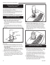
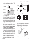
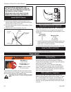
If the wall is brick or concrete, and contains no com-
bustible material, a 7” (178 mm) round penetration
hole is adequate. The wall thimble is not required. The
perforated straps of the horizontal termination provide
a method of attachment. These can either be threaded
through the opening or wall thimble (if used) and
screwed to the pipe or removed with a pair of tin snips
if not used. Use proper masonry fasteners to attach the
horizontal termination to the wall.
7. If a wall thimble is used, push the pipe (which is
connected to the appliance) carefully through the wall
thimble until the DIRECT-TEMP pipe becomes fully
engaged with the horizontal termination. If no thimble is
used, place the Trim Plate (TP) on the DIRECT-TEMP
pipe. Carefully push the DIRECT-TEMP pipe through
the wall until fully engaged with the horizontal termina-
tion. Secure the trim plate to the wall.
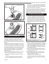
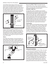
NOTE: If a vertical rise is necessary on the exterior side
of the building, a 14” (356 mm) and 36” (914 mm) Snor-
kel Termination (ST) is available. Follow the installation
procedures for horizontal terminations. If the snorkel
termination is to be located below grade, a window well
is recommended with adequate and proper drainage
as per local codes. Leave 2” (51 mm) clearance be-
low snorkel to prevent water from entering the snorkel
termination. Do not enclose the snorkel within a wall or
other type of enclosure and do not back fill. Ensure
that grade level slopes away from the building. (Fig. 40)
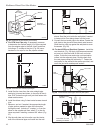
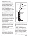
Vertical Installation (Fig. 44)
1. Determine the location of the appliance. Choose
a location which provides adequate clearance from
obstacles such as electrical wiring, conduit, framing
members, plumbing pipe, etc.
2. After positioning the appliance, determine where the
vent pipe will pass through the ceiling. This can be done
by using a plum bob or a small weight attached to a
string. Hold the plum bob from the ceiling moving it until
it lines up with the centerline of the outlet of the appli-
ance. Mark the position on the ceiling.
NOTE: Frame openings to the dimensions specified
in the framing table for the cathedral ceiling support
box (CCS), the ceiling support (SC) and wherever the
firestop spacer (FS) is being used.
3. Cut and frame the appropriate sized square hole
through the ceiling. Repeat the process for other ceiling
penetrations as necessary.
4. Determine and mark the roof penetration in the
same manner.
5. Cut a hole in the roof at this point large enough to
satisfy all clearance-to-combustible requirements as
specified by the appliance manufacturer’s installation
instructions.
6. Install the ceiling support cathedral ceiling support
box assembly, as appropriate.
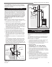
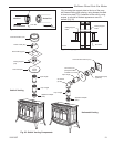
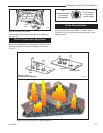
Vertical Termination
Approved Silicone
Sealant Here
Storm Collar
Flashing
Offset Support
Collar
Firestop
Spacer
Ceiling Support Collar
Ceiling
Support
Plate
Trim Plate
ST933
Fig. 44 Typical vertical venting configuration.
7. Determine the distance from the appliance outlet to
a point just above [approximately 12” (305 mm) to 24”
(610 mm)] either the cathedral ceiling support box or
the ceiling support plate and assemble lengths of pipe
to satisfy this distance. Do not attach assembly to appli-
ance.
8. Loosely position the support collar around the as-
sembled lengths (flared end down).
9. From above, lower the assembled pipe sections
down through the cathedral ceiling box or ceiling sup-
port plate and attach it to the appliance adapter. The
support collar should then be adjusted so that when
the assembled lengths of pipe are attached to the ap-
pliance, it rests on the bottom of the cathedral ceiling
support box on top of the ceiling support plate.
10. Tighten the tabs of the collar. Secure the sup-
port collar by inserting three (3) #8 x 1/4” sheet metal
screws through the support collar and the outer wall of
the pipe.
NOTE: If the cathedral ceiling support box assembly is
being used, it may be necessary to temporarily connect