


Special offers from our partners!

Find Replacement BBQ Parts for 20,308 Models. Repair your BBQ today.

2020
Radiance Direct Vent Gas Heater
20012697
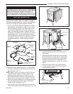
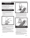
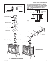
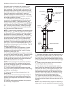
7. Install the appropriate roof support and flashing,
making certain that the upper flange of the flashing
base is below the shingles. (Fig. 33)
8. Install appropriate pipe sections until the vent run
reaches above the flashing. The enlarged ends of
the vent sections always face downward.
9. Install the storm collar and seal around the joints.
(Fig. 33)
10. Add additional vent lengths to achieve the proper
overall height.
11. Apply cement to the inner and outer termination col
-
lars and install the terminal cap.
ST222
vent thru ceiling
12/99
#7DVAIS
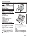
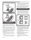
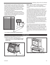
Attic Insulation
Shield
#7DVFS
Firestop in
Upper Floor
#7DVFS
Firestop in
Ceiling
Use Four
8d Nails
ST222
Fig. 32 Install firestops and attic insulation shield.
ST221
vent thru roof
12/99
Storm Collar
Sealant
Upper
edge of
flange goes
under upper
shingles
Flashing
#7DVSKV
(A, B, or
F) Roof
Support
Use three #5
sheet metal
screws at
each joint
ST221
Fig. 33 Roof support and flashing.
Selkirk Direct-Temp Metalbestos Direct
Vent System
Installation Instructions
1. Determine whether the length of pipe fits the appli-
ance outlet by attempting to engage the parts. If the
parts engage smoothly, proceed to Step 2. If ob-
structions, interference or loose fit is noted, contact
the appliance manufacturer or Selkirk Metalbestos
with the dimensions of the appliance outlet.
2. Slide the length of pipe over the appliance outlet a
minimum of 1¹⁄₂” and screw to the appliance outlet
collar using a minimum of two (2) #8 x 1/4” sheet
metal screws.
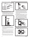
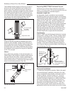
Appliance Adapter (AAV)
The appliance adapter (AAV) adapts DIRECT-TEMP to
most direct vent appliances incorporating outlet collars
configured to receive most common 4” (ID) 6⁵⁄₈” (OD) or
5” (ID) by 8” (OD) “Twist Lock” Style, direct vent sys-
tems.
The adapter incorporates two (2) indentations on the
outer wall of the inlet end, which are designed to “Twist
Lock” into place upon attachment to the appliance
outlet. Align the adapter indentations with the entry
slots of the appliance outlet and slide together. Turn the
adapter clockwise approximately one-quarter turn to
lock in place. The outlet end of the adapter is standard
DIRECT-TEMP construction.
Framing Dimension Table 1
Model DT Ceiling Support (CS) Cathedral Ceiling Wall Thimble
Diameter Firestop (FS) Support CCS) (WT)
4” 8¹⁄₄” x 8¹⁄₄” 10⁵⁄₈” x 10⁵⁄₈” 8¹⁄₄” x 8¹⁄₄”
5” 10¹⁄₈” x 10¹⁄₈” 14¹⁄₂” x 14¹⁄₂” 10¹⁄₈” x 10¹⁄₈”
Use of Sealant
It is not required to apply or use sealant on the inner
liner of DIRECT-TEMP. For outer wall joint sealing
considerations, follow appliance manufacturer recom-
mendations.
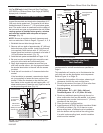
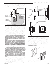
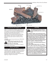
Joint Connection:
The pipe and elbows are assembled by inserting the
outlet (male) end of a length of pipe or elbow into the in-
let (female) end of an adjacent length of pipe or elbow.
Make sure the outlet end is fully seated within the inlet
end of the adjoining section and the gasket, located on
the inner liner of the inlet section is fully enclosed by the
inner liner of the outlet of the adjoining section. Push
in the Lock Tab such that it becomes seated within the
inward groove of the adjoining section. This locks the
joint in place. (Fig. 34)
Supporting DIRECT-TEMP: Vertical Support
Vertical installations can be supported by two methods:
Ceiling Support (CS) (used in flat ceiling installation)
comes with a support plate and a support collar. Install