


Special offers from our partners!

Find Replacement BBQ Parts for 20,308 Models. Repair your BBQ today.
1818
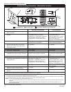
Radiance Direct Vent Gas Heater
20012697
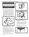
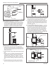
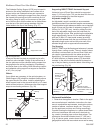
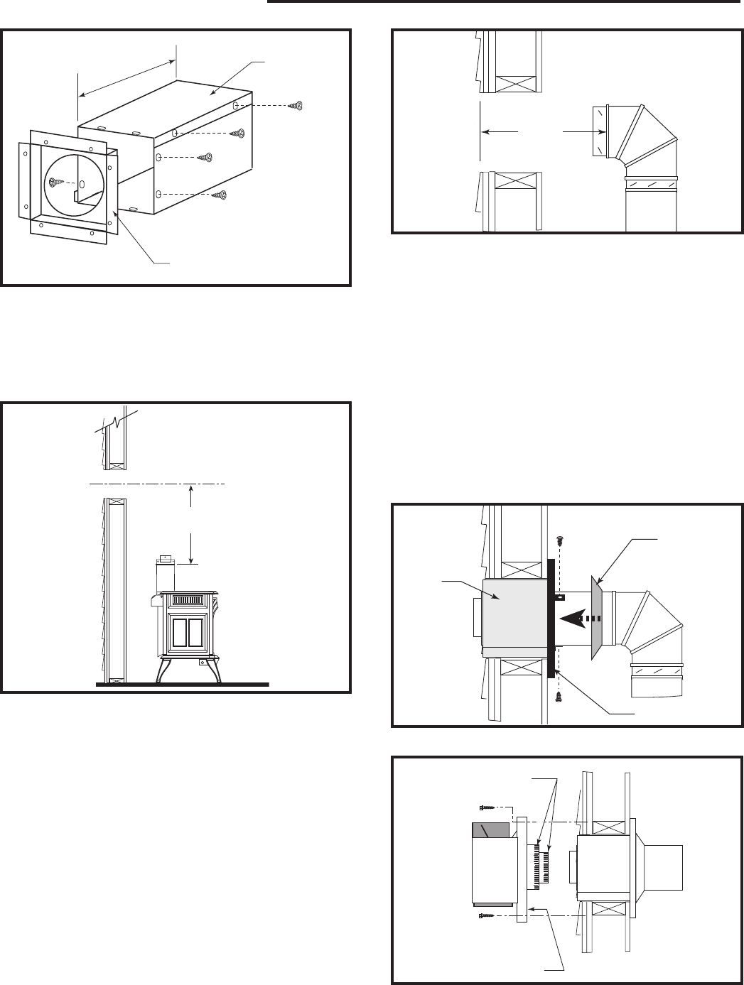
4. For CFM Vent Pipe only: If necessary, measure
to determine the vertical length (X) of pipe required
from the adapter pipe to the wall cutout centerline,
including a 2” overlap at the joint. (Fig. 26) use a
hacksaw or tin snips to trim the pipe as needed.
ZCS103
Zero Clearance Sleeve
& Firestop
12/6/99 djt
12”
(305mm)
Max. Length
Sleeve
#8 Sheet
Metal Screws
Firestop
ZCS103
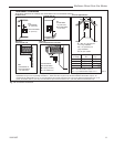
Fig. 25 Assemble the wall sleeve and firestop.
ST214a
measure vertical vent
12/6/99 djt
RADIANCE
X
ST652
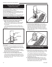
Fig. 26 Determine the vertical pipe length.
ST215
measure thru wall
12/6/99 djt
X
ST215
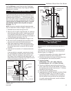
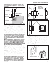
Fig. 27 Measure the horizontal length.
ST216
install pipe thru wall
12/6/99 djt
Trim Collar
Wall
Sleeve
Wall Plate
ST216
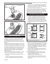
Fig. 28 Install the horizontal pipe and wall plate parts.
sleeve. Seal the joint inside the wall plate if needed
to keep cold air from being drawn into the home.
9. Connect the horizontal pipe to the elbow. Fasten the
wall plate to the pipe with three sheet metal screws.
Slide the trim collar up against the wall plate to cover
the screws. (Fig. 28)
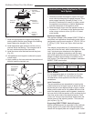
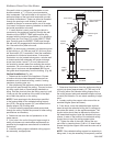
10. For both CFM and DuraVent Systems:
Install the
vent terminal. (Fig. 29) Apply high temperature seal-
ant one inch from the ends of the inner and outer
collars. Guide the inner and outer vent termination
collars into the adjacent pipes. Double check that
the vent pipes overlap the collars by 2”. Fasten the
termination to the wall with the screws provided, and
caulk the joint with weatherproof sealant.
ST217
install wall terminal
12/6/99 djt
Seal Both Termi-
nal Ends
Caulk Plate Joint with
Weatherproof Sealant
ST217
Fig. 29 Install the vent terminal.
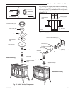
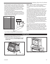
5. Install first the inner then the outer straight pipe
section(s), trimmed end down, to the point of the el-
bow. Drill 3 holes through each joint and fasten with
sheet metal screws.
6. Install the elbow using 3 sheet metal screws at each
joint.
7. Measure, and cut if needed, the appropriate length
of pipe section needed to make the connection
through the wall. Include a 2” overlap; i.e. from the
elbow to the outside wall face, about 2” or the dis-
tance required if installing a second 90° elbow. (Fig.
27)
8. Slip the wall plate and trim collar over the interior
end of the horizontal pipe and install into the wall