


Special offers from our partners!

Find Replacement BBQ Parts for 20,308 Models. Repair your BBQ today.
15
Radiance Direct Vent Gas Heater
20012697
ST347a
JUV
FK28
rheostat install
9/21/00
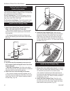
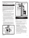
Rheostat
Retaining Collar
Rheostat Knob
ST347a
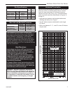
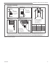
Fig. 18 Attach the fan rheostat.
Rheostat
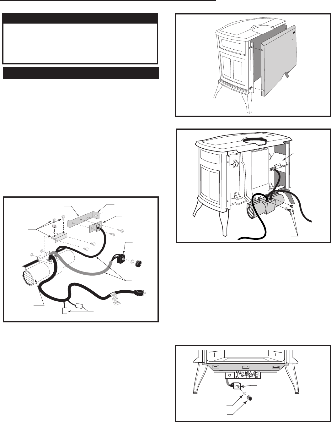
Install the Optional Fan
If you are installing the optional convection Fan Kit
#2767 (FK26), continue here. It is easiest to install fan
kit before connecting gas line. If you are not installing a
Fan Kit, go to Page 16, Venting System Assembly.
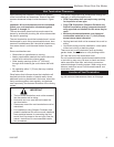
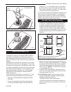
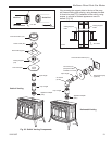
1. The fan kit includes a Blower Assembly and a Rheo
-
stat Assembly, connected by a cable. (Fig. 15) The
Blower Assembly mounts to the bottom rear of the
stove, and the Rheostat mounts to the valve cover-
plate. The assembly includes a ‘snapstat’ which au-
tomatically turns the fan On (or Off) above (or below)
approximately 109˚. The Rheostat also provides a
range of fan speed settings from Off (which overrides
the snapstat function) to High. Unpack and inspect
the Blower assembly. Confirm that the fan spins
freely.
ST147
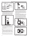
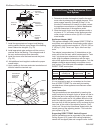
RDV40 remove rear shroud
10/99
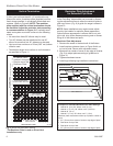
Fig. 16 Remove rear shroud.
ST147
ST473
Fan parts
#2767 FK26
9/29/00
Not
Used On
Radiance
Snapstat
Bracket
Snapstat/
Extension
Assembly
Rheostat
Assembly
ST473
Blower
Assembly
Fig. 15 Fan kit components.
Not Used On
RF Models
Not Used
On RF
Models
Connect to PC board on
RF models only
WARNING
This appliance is equipped with a three-prong
(grounded) plug for your protection against shock
hazard and should be plugged directly into a
properly grounded three-prong receptacle. Do not
cut or remove the grounding prong from this plug.
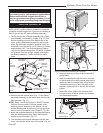
2. Remove the rear shroud panel (Fig. 17) and fasten
the blower assembly to the firebox back with the two
bolts provided. (Fig. 17)
NOTE: Steps 3 and 4 do not apply to RADVTC series
Comfort Control models. On these models, after
attaching blower assembly to the firebox, run the
spliced female leads to the front of the stove and at-
tach to back of Honeywell valve. (Page 33, Fig. 59)
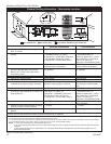
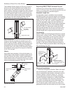
3. Attach the snapstat assembly to the snapstat bracket
with two sheet-metal screws. Attach the snapstat
bracket to the side shield. (Fig. 17)
4. The rheostat control switch attaches to the left side
of the valve bracket at the front of the stove. (Fig. 18)
ST149
rdv attach fan assy
10/99
Side Shield
Snapstat
Bolts
ST149
Fig. 17 Attach blower assembly and snapstat.
• Remove retaining nut from shaft of rheostat. (if
preinstalled)
• Insert the rheostat through the hole in the back
of the left side of the valve bracket, aligning the
locator pin with the smaller hole in that bracket.
• Thread the retaining nut onto the shaft of the
rheostat, tightening with a wrench. Do not over-
tighten.
• Attach the control knob to the rheostat shaft.
• Use the wire tie to secure the fan and rheostat
wire harnesses together.