


Special offers from our partners!

Find Replacement BBQ Parts for 20,308 Models. Repair your BBQ today.
17
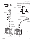
Radiance Direct Vent Gas Heater
20012697
ST651
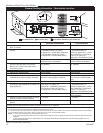
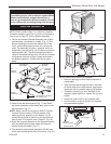
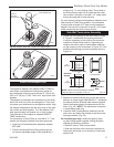
Fig. 23 Simpson Dura-Vent - install outer adapter pipe.
ST652
dura v
ent
attach outer assy
4/20/01 djt
ST649
dura vent
attach inner assy
4/20/01 djt
CEMENT
ST649
Inner Adpater Pipe
1/4-20 x
3/8” Phil-
lips Screws
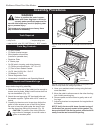
Fig. 22 Simpson DuraVent - install inner adpater pipe.
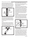
Install Vent Adapter Pipe
(Selkirk Corporation Vent Components)
The appliance adapter (AA) adapts DIRECT-TEMP to
most direct vent appliances incorporating outlet col-
lars configured to receive most common 4” (ID) by 6⁵⁄₈”
(OD) or 5” (ID) by 8” (OD) “Twist Lock” style, direct vent
systems.
The adapter incorporates two indentations on the outer
wall of the inlet end, which are designed to “Twist Lock”
into place upon attachment to the appliance outlet. Align
the adapter indentations with the entry slots of the appli-
ance outlet and slide together. Turn the adapter clock-
wise approximately one-quarter turn to lock in place.
The outlet end of the adapter is standard DIRECT-
TEMP construction.
For connection of Direct-Temp to units with 4” x 7” flue
outlets, the following methods have been approved:
• Install the Universal/Napoleon Appliance Adapter
4DT-AAN.
• Connect a standard Direct-Temp pipe length (do
not use an adjustable length in this application) a
minimum of 1¹⁄₂” over the flue outlet. The outside of
the Direct-Temp Length will fit inside the flue outlet
Secure with a minimum of two #8 x 1/4” sheet metal
screws and seal with hi-temp silicone.
For units factory equipped with appliance adapters from
other brands of Direct Vent systems, it is permissible
to simply slide a length of DT pipe over the appliance
adapter. Secure with a minimum of two #8 x 1/4” sheet
metal screws and seal with hi-temp silicone.
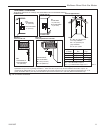
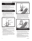
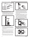
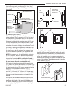
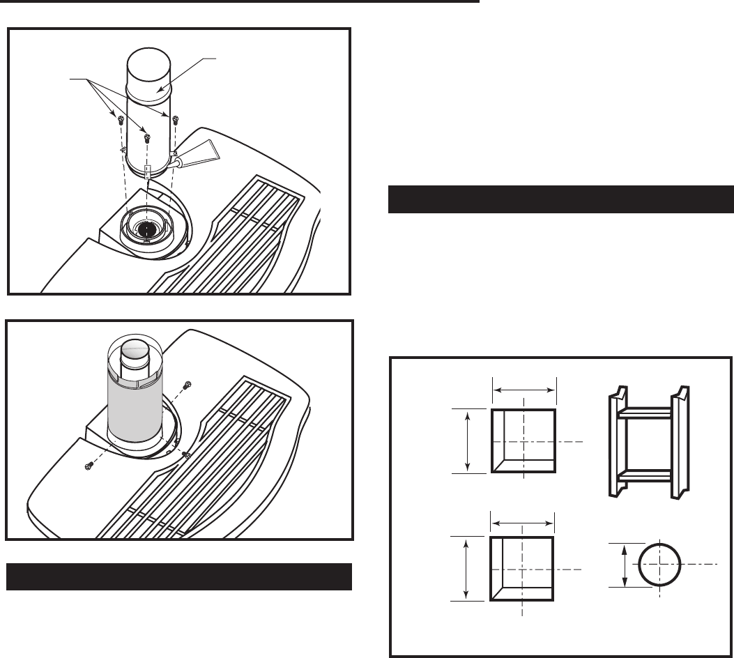
Side Wall Termination Assembly
1. Locate the vent opening on the wall. Refer to Page
6, Figure 5, to determine the opening centerline.
It may be necessary to first position the stove and
measure to find the hole location. Depending on
whether the wall is made of combustible materials,
cut the opening to the size shown in Figure 24. Com-
bustible wall openings must be framed as shown in
Figure 24.
VO584-100
Vent Opening
2/99 djt
9³⁄₈”
(240mm)
7¹⁄₂”
9³⁄₈”
(240mm)
Framing Detail
Combustible Wall
Noncombustible
Wall
VO584-100
Fig. 24 Locate vent opening.
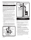
CFM System
DuraVent
System
10”
(254mm)
10”
(254mm)
NOTE: When Dura-Vent firestop is installed,
leave air space on top side of cut out.
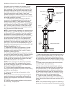
2. Measure the wall thickness and cut the wall sleeve
sections to proper length (MAXIMUM 12”). Assemble
the sleeve with the #8 sheet metal screws supplied.
Attach the firestop plate to the sleeve end with the
holes. (Fig. 25) NOTE: The wall sleeve is required
in combustible walls only.
3. Install the Wall Firestop/Sleeve assembly into the
wall cutout and fasten the firestop to the wall cutout
framing members. (Fig. 25)
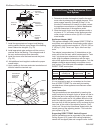
For DuraVent pipe only:
Install vent pipe by align-
ing the locking system together, sliding the pipes
together and twisting clockwise.
• Install 90° elbow. Twist lock as before.
• Slide the wall plate over horizontal run before at-
taching the horizontal run to the elbow. Fasten wall
plate to wall.