


Special offers from our partners!

Find Replacement BBQ Parts for 20,308 Models. Repair your BBQ today.

23
Radiance Direct Vent Gas Heater
20012697
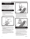
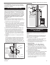
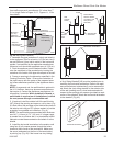
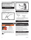
from traffic areas such as walkways if it is less than 7’
(2.1 m) high. Refer to Pages 10, 11, Figures 11, 12 for
more detail.
Snorkel Termination
Window Well
12” (305 mm) Minimum
Clearance Above Grade Level to
Air Intake
Grade Level
Sloped Away
From Building
Adequate
Drainage as per
Local Codes
Maintain 2”
(51 mm)
Clearance
Below Snorkel
ST929
Fig. 40 Below grade installation.
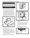
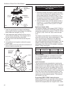
2. Assemble the pipe (and elbow if using) and attach it
to the appliance. Plan for a level to 1/4” per foot rise (6
mm per 305 mm) (from inlet to outlet) in the horizontal
system if not specified by the appliance manufacturer.
Horizontal runs should be supported every 4’ (122 cm).
3.
Push the appliance near the desired location. Deter-
mine the centerpoint of the penetration by locating the
centerline of the outlet of the pipe with respect to the wall.
4. Frame an opening to the dimension specified in the
Framing Dimension Table 1. Ensure the centerline of
the pipe lines up with the center of the prepared open-
ing unless otherwise specified by the appliance manu-
facturer.
NOTE: As a general rule, the wall thimble is optional in
the U.S. However, there may be some manufacturers
that require it. Contact the appliance manufacturer for
information if uncertain. When installed in Canada, a
wall thimble is required on all installations in which
the vent passes through a combustible wall.
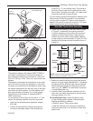
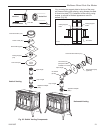
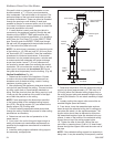
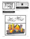
5. If required, install the outside half of the wall thimble
(WT) through the opening and screw or nail in place. (Fig.
41) Seal around the perimeter of the thimble face plate on
the exterior wall using an RTV silicone sealant to provide
protection from possible rain infiltration. (Fig. 41)
NOTE: The wall thimble accommodates wall thickness-
es of 4¹⁄₂” (114 mm) to 7¹⁄₂” (191 mm). If a larger range
is needed due to a thicker wall, it is permissible to field
fabricate a metal sleeve extension and attach it to the
shields.
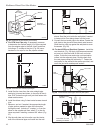
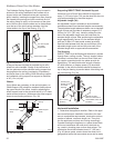
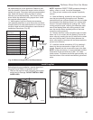
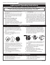
6. Install the horizontal termination to the exterior wall
using four (4) all purpose screws through the holes
located at each corner of the termination. Make sure
the arrow (embossed on the front of the termination)
is pointing up. (Fig. 42) If the house has vinyl siding,
Wall
Thimble
Shield
Seal with RTV
Silicone Sealant
on Exterior side
here (around
perimeter)
Wall Thimble
Shield
Wall
Thimble
Face
Plate
Wall Thimble
Face Plate
ST930
Fig. 41 Wall thimble.
Horizontal Termination
ST931
Fig. 42 Horizontal termination.
a Vinyl Siding Standoff (VS) must be installed prior to
installing the horizontal termination. Refer to the appli-
ance manufacturer to determine if one is recommend-
ed. Attach the vinyl siding standoff to the exterior side
of the wall (making sure it is level and centered with
respect to the opening) with screws (provided) at each
corner of the standoff. Attach the horizontal termination
to the standoff. (Fig. 43)
ST932
Selkirk standoff
6/07
Vinyl Siding Standoff
ST932
Horizontal Termination
Fig. 43 Vinyl siding standoff and horizontal termination.