


Special offers from our partners!

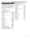
Find Replacement BBQ Parts for 20,308 Models. Repair your BBQ today.
19
Radiance Direct Vent Gas Heater
20012697
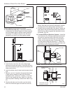
11. For CFM only: Install Charcoal Gray Pipe Rings
(#7FSDRG) or Polished Brass Pipe Rings (#7FSDRP)
at pipe joints, if desired.
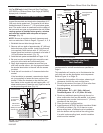
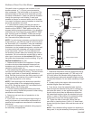
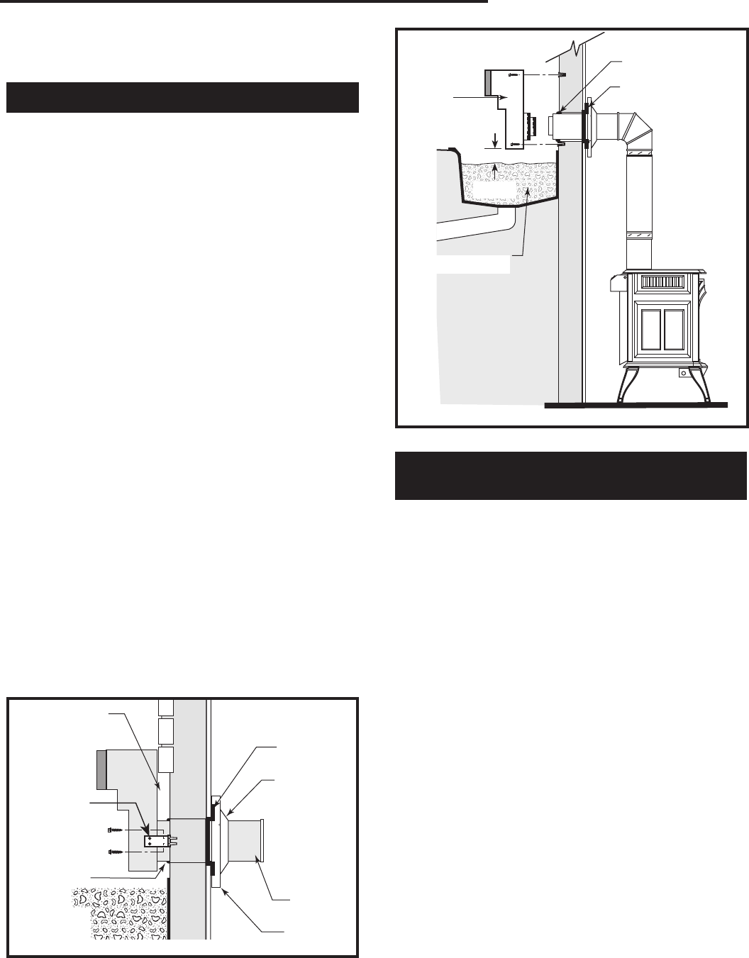
Vent Termination Below Grade
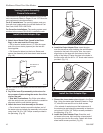
Install Snorkel Kit #7FSDVSKS when it is not possible
to meet the required vent termination clearances of 12”
(305 mm) above grade level. The snorkel kit will allow
installation depth of down to 7” (178 mm) below grade
level. The seven inches is measured from the center of
the horizontal vent pipe as it penetrates the wall. If the
venting system is installed below grade, a window
well must be installed with adequate and proper
drainage. (Fig. 31)
NOTE: Be sure to maintain side wall clearances and
vent run restrictions. Refer to Page 6, Figures 3, 4, 5, 6.
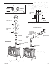
1. Establish the vent hole through the wall.
2.
Remove soil to a depth of approximately 16” (406 mm)
below the base of the snorkel. Install a window well
(not supplied). Refill the hole with 12” (305 mm) of
coarse gravel and maintain a clearance of at least 4”
(102 mm) below the snorkel. (Fig. 31)
3. Install the vent system as described on Pages 16-18.
4. Be sure to make a watertight joint around the vent
pipe joint at the inside and outside wall joints.
5. Apply high temperature sealant around the inner
and outer snorkel collars. Join the pipes and fasten
the snorkel termination to the wall with the screws
provided.
6. Level the soil to maintain a 4” clearance below the
snorkel.
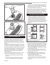
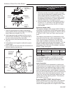
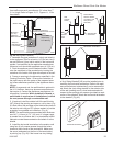
If the foundation is recessed, use extension brack
-
ets (not supplied) to fasten the lower portion of the
snorkel. Fasten the brackets to the wall first, and
then fasten to the snorkel with self-tapping #8 x 1/2”
sheet metal screws. Extend the vent pipes out as far
as the protruding wall face. (Fig. 31)
ST219
snorkel detail
12/6/99 djt
Recessed Wall
Sheet Metal
Screws and
Bracket
Wall Screws
and Anchors
Waterproof Seal
Around Pipe
ST219
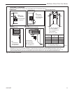
Fig. 30 Use extension brackets to mount snorkel against
recessed wall.
Firestop
Finishing
Collar
7” Pipe
Wall Plate
ST653
install snorkel
4/20/01 djt
RADIANCE
Waterproof Seal
Around Pipe
Firestop
Window Well
Drain
4” Clearance
Snorkel
Termination
Cap
Wall Screws
and Anchors
ST653
Gravel
Fig. 31 Snorkel kit installation.
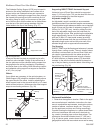
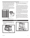
Vertical (Through the Roof)
Vent Assembly
Make certain the vent system conforms to all other
requirements for vertical termination as specified on
Page 9.
This installation will require you to first determine the
roof pitch and use the appropriate vent components.
Refer to Figure 11 on Page 10.
1. Locate the final position of the stove, observing all
clearances for both the vent and the stove.
2. Plumb to the center of the inner (4”) flue collar from
the ceiling above, and mark that location.
3. Cut the opening:
CFM System: 9
³⁄₈” x 9³⁄₈” (240 x 240 mm)
DuraVent System: 10” x 10” (254 x 254 mm)
4. Plumb any additional opening through the roof or
other construction that may be needed. In all cases,
the opening must provide a minimum of 1” (25 mm)
clearance to the vent pipe.
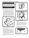
5. Place the stove in its final position.
6. Install firestop(s) #7DVFS and Attic Insulation Shield
#7DVAIS as needed. (Fig. 32) If there is a room
above ceiling level, a firestop must be installed on
both the bottom and top sides of the ceiling joists.
If an attic is above ceiling level, an attic insulation
shield must be installed.