


Special offers from our partners!

Find Replacement BBQ Parts for 20,308 Models. Repair your BBQ today.

25
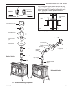
Radiance Direct Vent Gas Heater
20012697
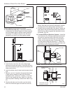
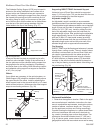
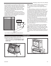
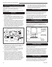
Minimum Height
Above Roof
ST934
minimum height
6/07
Minimum
Roof Pitch Height
Flat to 7/12 1’0”
Over 7/12 to 8/12 1’6”
Over 8/12 to 8/12 2’0”
Over 9/12 to 10/12 2’6”
Over 10/12 to 11/12 3’3”
Over 11/12 to 12/12 4’0”
Over 12/12 to 14/12 5’0”
Over 14/12 to 16/12 6’0”
Over 16/12 to 18/12 7’0”
Over 18/12 to 20/12 7’6”
Over 20/12 to 21/12 8’0”
Fig. 45 Minimum Height Above Roof Requirements
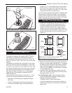
the assembled pipe to the appliance. Determine and
mark the location of where the support collar will be at-
tached to the pipe. Disconnect and remove assembled
pipe. Attach the support collar per Step 10 (where
marked) and reinstall assembly. This is due to limited
space within the cathedral ceiling support box. Install
any required offset supports.
11. Add lengths of pipe and firestop as necessary
until assembly extends to a point above the roof which
complies with local code requirements for minimum ter-
mination height and with the appliance manufacturer’s
installation instructions. (Fig. 45)
NOTE: Whenever DIRECT-TEMP penetrates through a
ceiling, a floor or a wall, it must be firestopped.
12. Using a level, make sure the system is perfectly
vertical.
13. Slide the flashing, suitable for the roof pitch, down
over the pipe protruding through the roof. Recheck
orientation and use a silicone sealant around and under
the perimeter of the flashing where it is in contact with
the roof. Secure the flashing with roofing nails. Finish
roofing around the pipe, covering the sides and upper
ares of the flashing base with roofing material. How-
ever, be sure the lower unnailed portion of the base
covers the roofing material.
14. Position the storm collar around the pipe and slide
down until it is in contact with the flashing. Secure the
storm collar by inserting the two (2) tabs into the raised
slots and fold tabs back. Seal the area between the
storm collar and the vent pipe with a silicone sealant to
prevent rain infiltration.
15. Install the vertical termination (VC) by inserting it
down into the top most section of pipe until it is fully
seated. Depress lock tab to secure the cap to the pipe.
NOTE: In high wind areas, it is recommended to screw
termination to the pipe with two (2) #8 x 1/4” sheet
metal screws. The screws should be approximately 3/4”
from the bottom of the vertical termination’s galvanized
collar.
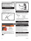
ST139
Radiance
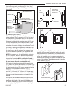
remove front
4/20/01 djt
ST139
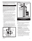
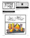
Fig. 46 Remove the stove front.
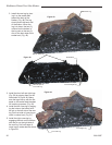
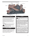
Install Log Set
Before beginning log installation, remove stove front
and glass frame. Refer to Figures 44 and 47.
1. Remove the logs from their packaging and inspect
each piece for damage. DO NOT INSTALL DAM-
AGED LOGS.
ST141
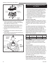
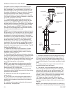
pull glass latch
10/99
ST141
Fig. 47 Release the latches to remove the glass frame.