


Special offers from our partners!

Find Replacement BBQ Parts for 20,308 Models. Repair your BBQ today.
9
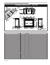
CDV Series Direct Vent Gas Fireplace
20010175
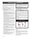
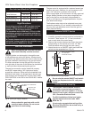
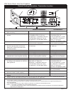
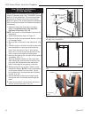
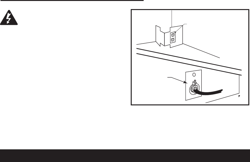
The electrical junction box has been fitted standard on
this model to allow for the easy connection of an op-
tional fan kit.
To connect the electric box to the house electrical sup
-
ply follow the steps below.
1. Unscrew the retaining screw holding the electric
cover to the outside of the unit. (Fig. 7)
2. Remove the knockout from the electric cover plate.
3. Insert the wire connector through the hole in the
electric cover plate and secure.
4. Insert the house wire through the connector on the
cover plate.
5. Secure the wires from the receptacle to the incoming
line.
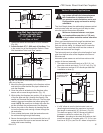
6. The receptacle has four wires connected to it. The
receptacle is set up for a split system. The top plug
of the receptacle is wired separately from the bottom
one.
7. Green is ground. White is neutral, Black and red are
line voltage to each plug on the receptacle.
Ensure that the power to the supply line
has been disconnected before commenc-
ing this procedure.
FP1597
Fig. 7 Electric receptacle.
FP1597
receptacle install
12/05
OUTSIDE
INSIDE
BACK OF UNIT
Electric Receptacle
Electric Receptacle
Cover Plate
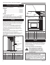
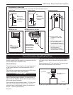
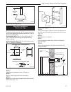
Your fireplace is approved to be vented either through
the side wall, or vertically through the roof.
• Only CFM Corporation venting components specifi-
cally approved and labelled for this fireplace may be
used.
• Vent terminations shall not be recessed into a wall or
siding.
• Horizontal venting which incorporates the twist lock
pipe must be installed on a level plane without an
inclining or declining slope.
• Horizontal venting which incorporates the use of flex
venting shall have an inclining slope from the unit of
1” (25 mm) per 24” (610 mm).
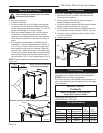
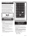
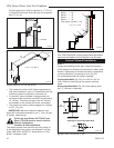
General Venting
There must not be any obstruction such as bushes,
garden sheds, fences, decks or utility buildings within
24” (610mm) from the front of the termination hood.
Do not locate termination hood where excessive snow
or ice build up may occur. Be sure to check vent termi-
nation area after snow falls, and clear to prevent ac-
cidental blockage of venting system. When using snow
blowers, make sure snow is not directed towards vent
termination area.
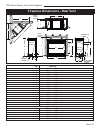
Location of Vent Termination
It is imperative the vent termination be located observ-
ing the minimum clearances as shown on the next
page.
*Check with local codes or in absence of same with
CSAB149.1 Installation Codes (1991) for Canada or fol-
low the current National Fuel Gas Code, ANSI Z223.1/
NFPA 54 for installations in the USA.