


Special offers from our partners!

Find Replacement BBQ Parts for 20,308 Models. Repair your BBQ today.
25
CDV Series Direct Vent Gas Fireplace
20010175
1
2
3
4
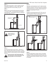
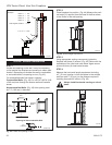
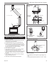
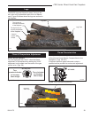
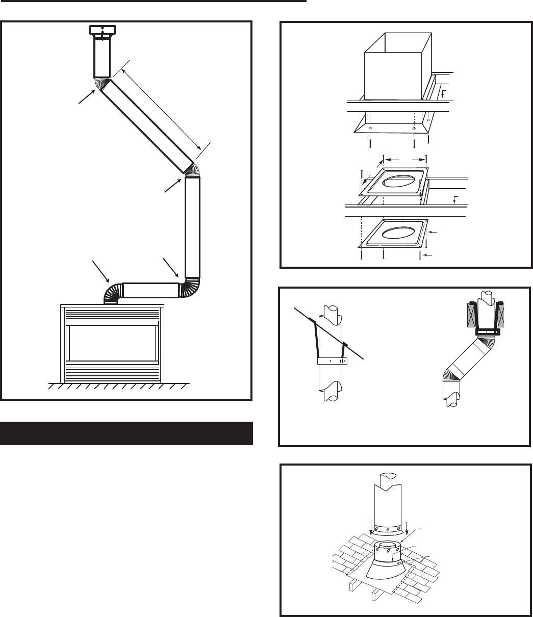
Max. 8' (2.4m)
FP1245
through the roof
90 & 45 degree
12/02
1 + 2 + 3 + 4 = 270°
FP1245
Fig. 51 Typical offset application.
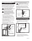
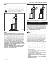
Vertical Through-the-Roof Installation
1. Locate your fireplace.
2. Plumb to center of the (4” (102 mm) flue collar from
ceiling above and mark position.
3. Cut opening equal to 9
³⁄₈” x 9³⁄₈” (240 x 240 mm).
4.
Proceed to plumb for additional openings through the
roof. In all cases, the opening must provide a minimum
of 1” (25 mm) clearance to the vent pipe, i.e., the hole
must be at least 9³⁄₈” x 9³⁄₈” (240 x 240 mm).
5. Place fireplace into position.
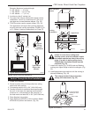
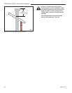
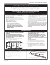
6. Place firestop(s) #7DVFS or Attic Insulation Shield
#7DVAIS into position and secure. (Fig. 52)
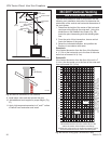
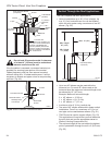
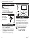
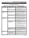
7. Install roof support (Fig. 53) and roof flashing making
sure upper flange of flashing is below the shingles.
(Fig. 53)
8. Install appropriate pipe sections until the venting is
above the flashing. (Fig. 53)
9. Install storm collar and seal around the pipe.
CFM100
Firestop-Vertical
09/20/00
11"
11"
Attic Insulation
Shield
Joist
Ceiling In-
stallation
Joist
Upper Floor
Firestop Spacer
Nails (4)
CFM100a
Fig. 52 Place firestop spacer(s) and secure.
CFM110
Typical ceiling/roof support
10/90
Typical Roof Support
Application
Typical Ceiling Sup
-
port Application
CFM110
Fig. 53 Roof and ceiling supports.
TWL101a
Twist Lock Pipe
2/8/99 djt
#8 Sheet Metal Screws
(3 per joint)
Sealant
Storm Collar
TWL101a
Fig. 54 Roof flashing.
10. Add additional vent lengths for proper height. (Fig.
55)
11. Apply high temperature sealant to 4” and 7” collars.