


Special offers from our partners!

Find Replacement BBQ Parts for 20,308 Models. Repair your BBQ today.
17
CDV Series Direct Vent Gas Fireplace
20010175
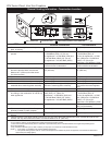
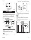
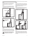
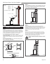
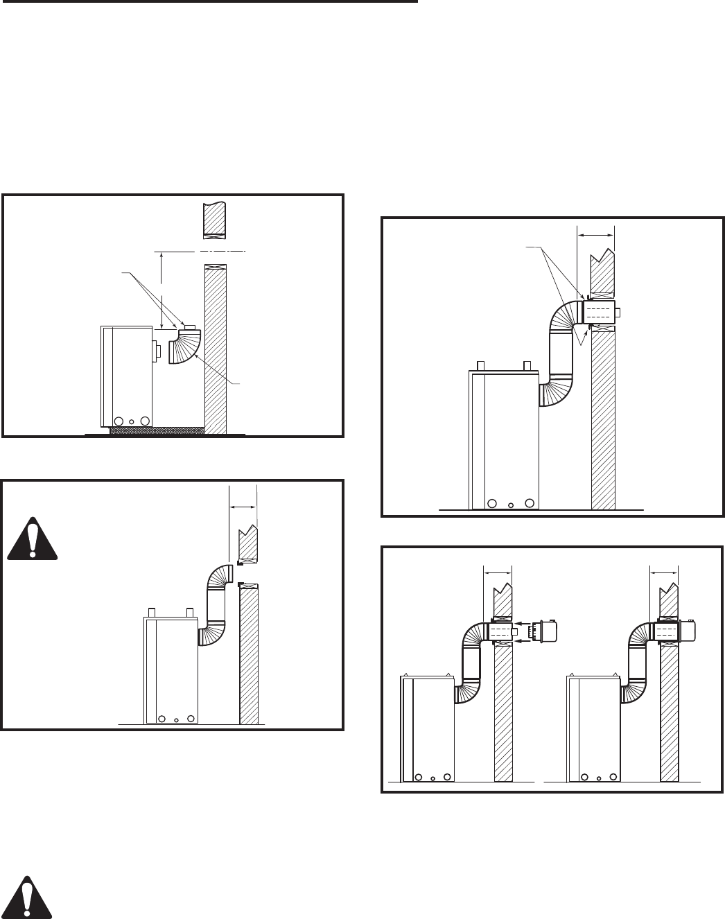
STEP 2
Slide venting component on collar of fireplace. Secure
component to fireplace by running a screw (self-tap
-
ping) through tab & into outer casing. (Fig. 26)
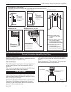
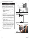
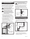
STEP 3
Measure the horizontal length requirement including a
2” (51 mm) overlap, i.e. from the elbow to the outside
wall finish plus 2”, or the distance required if installing a
second 90° elbow. (Fig. 27)
CFM136
Rear Vent horizontal length
2/26/01 sta
X
Always install hori-
zontal venting on a
level plane.
CFM136
Fig. 27 Measure horizontal length including 2” overlap.
�
CFM143
2/2/01 sta
Ensure Pipes are
Concentric
CFM143a
Fig. 26 Always start vertical run with 7TCDV90 on 36CDVR
unts.
7TCDV90
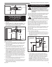
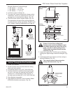
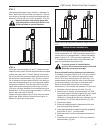
STEP 4
Use appropriate length of pipe section - telescopic or
fixed - and install the horizontal vent sections. A starter
section of pipe which goes through the wall is packaged
with the 7TCRVT kit, and can be cut to suit if necessary.
(Fig. 28)
Sealing vent pipe and firestop gaps with
high temperature sealant will restrict cold
air being drawn in around fireplace.
CFM137
Rear Vent length
2/26/01 sta
X
High
Temperature Sealant
CFM137
Fig. 28 Apply high temperature sealant.
CFM138
4", 7" collar
2/26/01 sta
X
X
CFM138
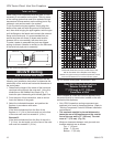
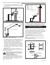
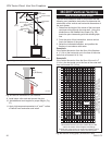
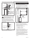
Fig. 29 Horizontal length requirement.
STEP 5
Guide the vent termination’s 4” and 7”
collars into their
respective vent pipes. Double check that the vent pipes
overlap the collars by 2” (51 mm). Secure the termination
to the wall with screws provided and caulk around the
wall plate to weatherproof. (Fig. 29)
STEP 6
Support the horizontal pipes every 36” (914 mm) with
metal pipe straps. Make sure that the horizontal vent
pipe is installed on a level horizontal plane.
STEP 7
Re-check the fireplace to make sure that it is levelled,
properly positioned, and nailed or screwed to the floor.
If applied, the fireplaces adjustable frame drywall strips
(nailing flanges) should be fastened. Refer to “Framing
& Finishing”.