


Special offers from our partners!

Find Replacement BBQ Parts for 20,308 Models. Repair your BBQ today.
22
CDV Series Direct Vent Gas Fireplace
20010175
1
2
3
4
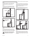
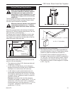
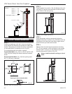
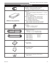
Example:
Elbow 1 = 90°
Elbow 2 = 45°
Elbow 3 = 45°
Elbow 4 = 90°
Total angular variation = 270°
1 + 2 + 3 + 4 = 270°
FP1239
Fig. 42 Maximum number of elbow degrees.
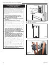
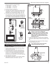
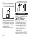
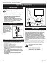
STEP 1
Locate vent opening on the wall. It may be necessary
to first position the fireplace and measure to obtain hole
location. Depending on whether the wall is combustible
or noncombustible, cut opening to size. (Fig. 43)
For combustible walls first frame in opening.
Combustible Walls:
(Fig. 43) Cut a 9³⁄₈”H x 9³⁄₈”W (240
x 240 mm) hole through the exterior wall and frame as
shown.
Noncombustible Walls:
(Fig. 43) Hole opening must
be 7¹⁄₂” (190 mm) in diameter.
Vertical Sidewall Installations
VO584-100
Vent Opening
2/99 djt
Vent Opening for Combustible Wall
9³⁄₈”
(240mm)
9³⁄₈”
(240mm)
Fireplace Hearth
Framing
Detail
Opening for Noncombustible Wall
7¹⁄₂”
(190mm)
VO584-100
Fig. 43 Locate vent opening on wall.
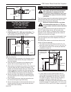
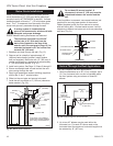
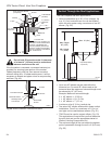
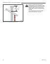
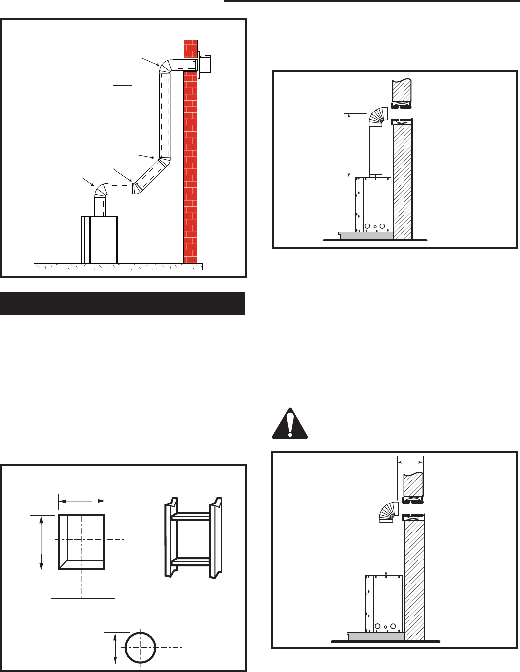
STEP 2
Place fireplace into position. (Fig. 44) Measure the verti
-
cal height (X) required from the base of the flue collars
to the center of the wall opening.
X
FP1240
Fig. 44 Vertical height requirement.
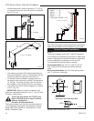
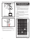
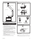
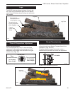
STEP 3
Using appropriate venting component(s) attach to
fireplace with three (3) screws. (Fig. 45) Follow with the
installation of the inner and outer elbow. Again secure
joints with three (3) sheet metal screws.
STEP 4
Measure the horizontal length requirement including
a 2” (51 mm) overlap, ie from the elbow to the outside
wall face plus 2” (51 mm) (or the distance required if
installing a second 90° elbow). (Fig. 45)
Always install horizontal venting on a level
plane.
X
FP1241
Fig. 45 Horizontal length requirement.