


Special offers from our partners!

Find Replacement BBQ Parts for 20,308 Models. Repair your BBQ today.

7
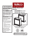
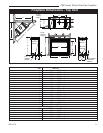
CDV Series Direct Vent Gas Fireplace
20010175
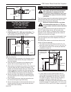
Noncombustible materials such as brick or tile may be
extended over the edges of the face of the fireplace.
DO NOT cover any vent or grille panels.
If a Trim Kit is going to be installed on the fireplace, the
brick or tile will have to be installed flush with the edges
of the fireplace.
Final Finishing
36CDVR / 36CDVT
Certified To
ANSI Z21.88b-2003 / CSA 2.33b-2003
Vented Gas Fireplace Heaters
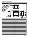
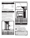
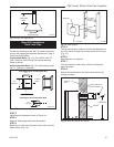
Framing and Finishing
Check fireplace to make sure it is levelled
and properly positioned.
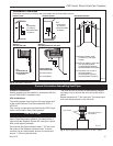
To mount the appliance:
1. Choose the location.
2. This unit comes with four (4) flanges pre-mounted
on both sides of the fireplace to allow two different
drywall thicknesses to be used. Flange “A” is for 1/2”
drywall while flange “B” is for 5/8” drywall.
3. Bend the desired flanges out 90° on both sides of
the fireplace. Slide the fireplace into the framed
opening until the flanges contact the front surfaces
of the framing. Level the unit and secure it firmly in
place.
4. The standoffs are adjustable for different drywall
thicknesses. The unit is shipped from the factory at
1/2” (13 mm). Loosen the four (4) screws securing
each standoff to the top of the fireplace. Slide the
standoff back. Tighten the screws. This yields a 5/8”
(16 mm) thick drywall space. Removing the standoff
and having the tabs on the standoff face the rear of
the unit yields a 3/4” (19 mm) drywall space. (Fig. 4)
NOTE: Drywall must stop at standoffs and not touch
top of unit.
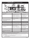
36CDVRRN Units: GFRL1J0
36CDVTRN Units: GFTN1J0
Gas Specifications
Max. Min.
Input Input
Model Fuel Gas Control BTU/h BTU/h
36CDVRRN Nat Millivolt 21,000 14,700
36CDVRRP* Prop Millivolt 21,000 15,750
36CDVTRN Nat Millivolt 21,000 14,700
36CDVTRP* Prop Millivolt 21,000 15,750
*Using conversion kit
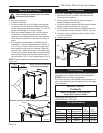
A
B
FP1603
flange location
12/05
Fig. 4 Nailing flanges and standoffs.
Flange Drywall
Position Depth
A 1/2” / 13 mm
B 5/8” / 16 mm
Flange Location for Desired
Drywall Depth at Header
FP1603a
standoff location
3/06
Screws
Tabs
Standoff Location for Desired Drywall Depth at Header
FP1603a
FP1603
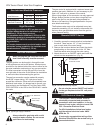
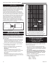
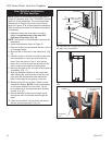
Hood Installation
CAUTION: Hood MUST be permanently installed.
1. Remove top louvre. Carefully remove hood from
inside top louvre opening.
2. Remove three (3) sheet metal screws in bottom
flange of fireplace surround top.
3. Install the hood by aligning the three holes in bottom
flange of fireplace surround top. (Fig. 4a)
4. Secure hood to bottom flange of fireplace surround
top using three screws removed in Step 2. (Fig. 4a)
5. Carefully remove protectors under the relief plates
on top of the firebox.
6. Replace top louvre.
Hood
Sheet
Metal
Screws
FP1609
Fig. 4a Secure hood to fireplace with sheet metal screws.