


Special offers from our partners!

Find Replacement BBQ Parts for 20,308 Models. Repair your BBQ today.
15
CDV Series Direct Vent Gas Fireplace
20010175
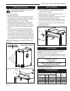
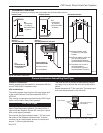
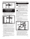
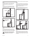
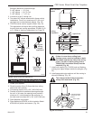
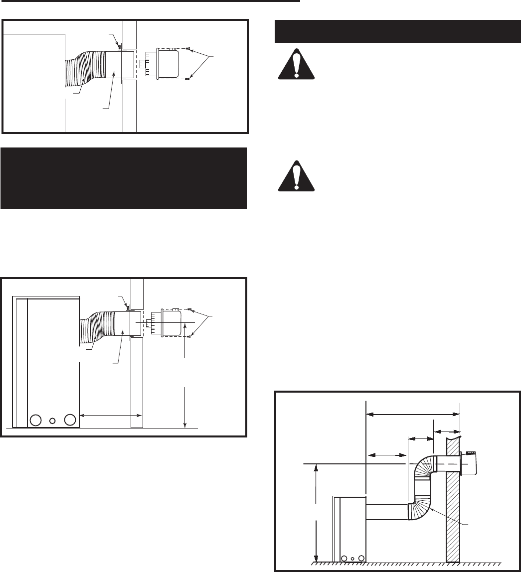
Screw
Collar
Screws
FP1605
Fig. 19 Secure collar in place, slide termination into collar.
Flex Vent
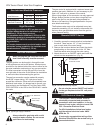
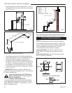
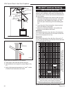
Rear Wall Vent Application
* Exterior Outside Wall
20” - 32” (508 - 813 mm)
From Rear of Unit *
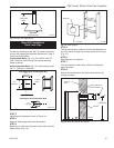
1. Determine where the termination is to be installed.
(Fig. 20)
2. Locate the hole 27¹⁄₄” (692 mm) off the floor. This
is the center line of the termination. Refer to “Rear
Wall Installation Twist Lock Pipe” section.
CFM141
2/2/01 sta
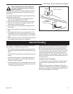
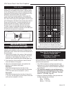
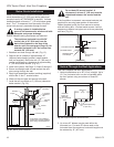
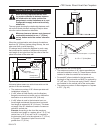
Maximum
20 ft. (6.1m)
7.5'
(2.3m)
15 ft.
(4572mm)
48"
(1.2m)
12"
(305mm)
Vertical Dimension
7¹⁄₂’ Minimum When
Horizontal Run is
20’
CFM141
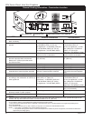
Fig. 21 Maximum number of 90° elbows is three (3).
7TCDV90
or
7TDV90
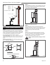
27”
(692 mm)
20” - 32”
(508 - 813 mm)
Screw
Screws
Flex Vent
Collar
FP1605a
Fig. 20 The centerline of the termination must be 27¹⁄₄”
(692 mm) off the floor.
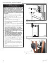
3. Mount the flex pipe assembly to the fireplace collars
and twist the collar that the flex pipe is attached to
onto the fireplace.
4. Once the collar is twisted onto the fireplace collar,
secure with a screw through the tab. (Fig. 15)
5.
While sliding the fireplace into position, lift up the end
of the flex pipe and slip it through the firestop. *Be
careful not to extend the flex too much. The flex pipe
needs to have an immediate rise before going hori-
zontal. NOTE: Be careful not to distort the outer flex
as this will affect the performance of the fireplace.
6. Secure the collar to the firestop by bending the tab
out on the firestop and running a screw through the
tab and collar.
7. From outside the house, slide the termination onto
the collars sticking through the firestop.
8. Secure the termination to the house with the four (4)
screws provided. Be sure to seal around the termi-
nation and house cladding.
Vertical Sidewall Applications
Since it is very important that the vent-
ing system maintain its balance between
the combustion air intake and the flue
gas exhaust, certain limitations as to vent
configurations apply and must be strictly
adhered to.
The Vent Graph shows the relationship between vertical
and horizontal side wall venting and will help to deter-
mine the various dimensions allowable.
Minimum clearance between vent pipes
and combustible materials is 1”(25 mm)
on top, bottom and sides unless otherwise
noted.
When vent termination exits through foundations less
than 20” below siding outcrop, the vent pipe must
flush up with the siding. It is always best to locate the
fireplace in such a way that minimizes the number of
offsets and horizontal vent length.
The horizontal vent run refers to the total length of vent
pipe from the flue collar of the fireplace to the face of
the outer wall.
Horizontal plane means no vertical rise exists on this
portion of the vent assembly.
• The maximum horizontal vent run is 20 ft. (6.1 m)
when the vertical vent rise is 7¹⁄₂ ft. (2.3 m). (Fig. 21)
• The maximum number of 90° elbows per side wall
installation is three (3).
• If a 90° elbow is used in the horizontal vent run
(level height maintained) the maximum horizontal
vent length is reduced by 36” (914 mm). (Fig. 22)
This does not apply if the 90° elbows are used to
increase or redirect a vertical rise. (Fig. 23)
Example: According to the chart the maximum hori-
zontal vent length in a system with a 7.5’ (2.3 m) ver-
tical rise is 20’ (6 m) and if a 90° elbow is required in