


Special offers from our partners!

Find Replacement BBQ Parts for 20,308 Models. Repair your BBQ today.
14
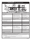
CDV Series Direct Vent Gas Fireplace
20010175
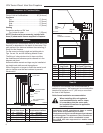
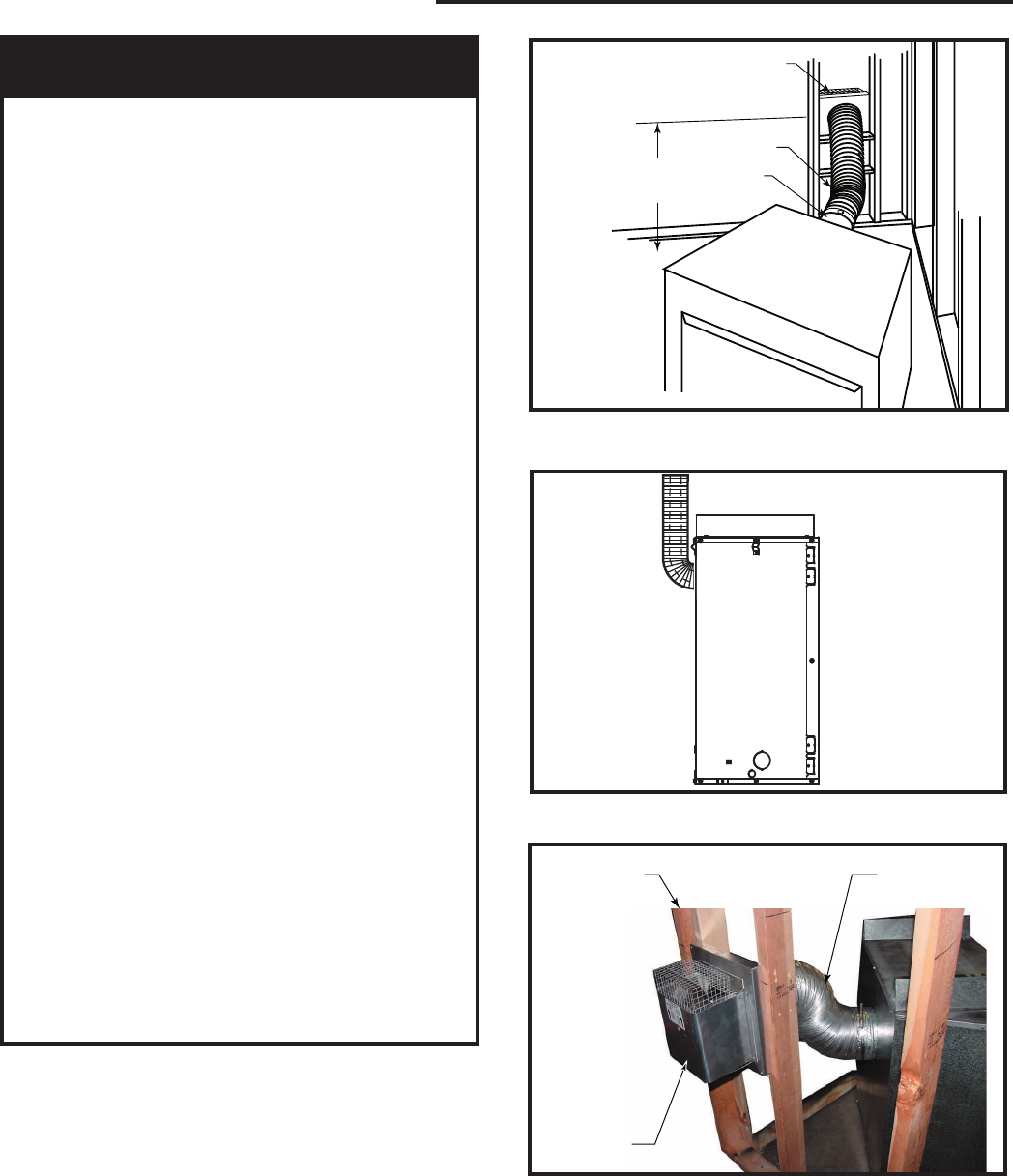
Rear Wall Vent Installations -
45° Flex Vent Pipe
NOTE: Under no circumstances can ridged pipe or
a rigid 45° elbow be used. The 7TCDV45KT must be
used in a corner installation. The corner placement
dimensions on Page 4 of the manual must be ad-
hered to! Figures 16 & 18 show general installations.
Refer to instructions below for a detailed description
of installation.
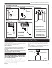
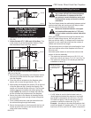
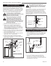
1. Determine where the termination is to be in
-
stalled. Locate the center of the hole 29¹⁄₂”
(749 mm) off the floor. (Fig. 16)
NOTE: The location of the termination hole must be
adhered to!
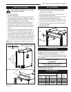
2. Install the firestop as shown on Page 12.
3. Remove the flex vent and extend the flex vent out
to its longest length.
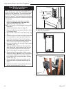
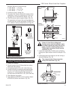
4. Bend the tab on the back of the fireplace up. (Fig.
14)
5. Insert the collar on the flex vent that has the twist
lock embosses on it onto the collar of the fire-
place. Twist the collar to “lock it” onto the fire-
place. Run a screw through the tab and into the
collar to secure the collar onto the fireplace.
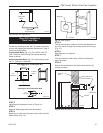
6. Bend the flex pipe up 90° as close to the fireplace
as possible. (Fig. 17)
7. Slide the fireplace partially into the corner and,
while holding the vertical portion of the flex vent
pipe, grab the exposed end collar and bend it
down to the height of the opening in the wall.
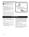
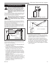
8. While pushing the unit in place, slide the collar
through the firestop. NOTE: It may be necessary
to trim some material off of the collar. The col-
lar is made long to accommodate brick finished
houses. (Fig. 19)
9. Secure the collar in place by running a screw
through the tab in the firestop and through the
collar.
10. Slide the termination into the collar and secure
with the 4 screws provided. (Fig. 19)
FP1473
corner flex install
4/04 djt
C
L
to Floor
29
”
(749 mm)
Termination
Flex Section
Appliance
Collars
FP1473
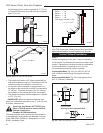
Fig. 16 Grasp the vent pipe close to the collar and bend to
45° angle. Do not exceed 45°.
Fig. 17 Bend flex pipe up 90° as close to fireplace as pos-
sible.
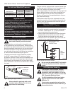
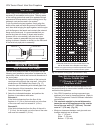
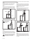
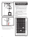
FP1604
Do Not Exceed
45° Bend
Corner
Framing
Termination
FP1606
Fig. 18 Rear view of corner installation.