


Special offers from our partners!

Find Replacement BBQ Parts for 20,308 Models. Repair your BBQ today.
12
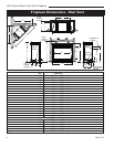
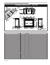
CDV Series Direct Vent Gas Fireplace
20010175
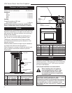
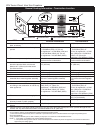
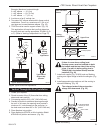
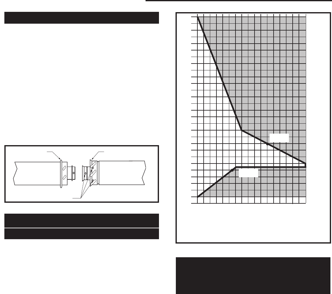
The vent chart should be read in conjunction with the
following vent installation instructions to determine the
relationship of the vertical and horizontal dimensions of
the vent system.
1. Determine the height of the center of the horizontal
vent pipe exiting through the outer wall. Using this
dimension on the Sidewall Vent Graph (Fig. 11)
locate the point intersecting with slanted graph line.
2. From the point of this intersection, draw a vertical
line to the bottom of the graph.
3. Select the indicated dimension, and position the
fireplace in accordance with same.
Example A:
If the vertical dimension from the floor of the
fireplace is 11’ (3.4 m) the horizontal run to the face
of the outer wall must not exceed 14’ (4.3 m).
Example B:
If the vertical dimension from the floor of the unit is
7’ (2.14 m), the horizontal run to the face of the outer
wall must not exceed 8¹⁄₂’ (2.6 m).
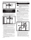
How to Use the Vent Graph
Horizontal dimension from the outside face of the
wall to the center of the fireplace vent flange
Sidewall vent graph showing the relationship between vertical
and horizontal dimensions for a Direct Vent flue system.
Vertical dimension from the floor of the unit
to the center of the horizontal vent pipe
3
4
5
6
7
8
9
10
11
12
13
14
15
16
17
18
19
20
21
22
23
24
25
26
27
28
29
30
3 4 5 6 7 8 9 10 11 12 13 14 15 16 17 18 19 20
eg: A
eg: B
CFM102
DV Graphic
9/28/00 sta
Fig. 11 Sidewall venting graph. (Dimensions in feet)
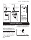
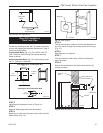
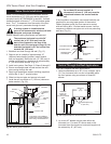
Rear Wall Venting Applications
* Exterior Outside Wall
7” (178 mm) to 13” (330 mm)
From Rear of Unit *
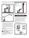
When installed as a rear vent unit this appliance may
be vented directly to a termination located on the rear
wall behind the appliance.
• Only CFM Corporation venting components are
approved to be used in these applications. (Refer to
“Venting Components” listed for different installation
requirements)
• The maximum straight horizontal distance be-
tween the rear of the appliance and the outside
face of the rear wall is 13” (330 mm). The mini-
mum is 7” (178 mm). (Fig. 12)
• Minimum clearances between vent pipe and com-
bustible materials are as follows:
Top - 1” (25 mm)
Sides - 1” (25 mm)
Bottom - 1” (25 mm)
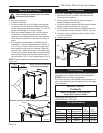
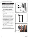
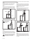
Twist Lock Pipes
When using CFM Corporation twist-lock pipe, it is not
necessary to use sealant on the joints. The only areas
of the venting system that need to be sealed with high
temperature silicone sealant are the sliding joint of any
telescopic vent section used in the system.
To join the twist lock pipes together, simply align the
beads of the male end with the grooves of the female
end, then while bringing the pipe together, twist the pipe
until the flange on the female end contacts the external
flange on the male end. It is recommended that you
secure the joints with three (3) sheet metal screws,
however this is not mandatory with twist lock pipe.
To make it easier to assemble the joints we suggest
putting a lubricant (Vaseline or similar) on the male end
of the twist lock pipe prior to assembly.
36CDVR Venting
TWL100
Twist Lock Pipe
3/12/99 djt
Male End Female End
Screw Holes
TWL100
Fig. 10 Twist-lock pipe joints.