


Special offers from our partners!

Find Replacement BBQ Parts for 20,308 Models. Repair your BBQ today.
11
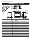
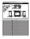
CDV Series Direct Vent Gas Fireplace
20010175
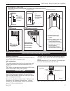
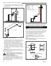
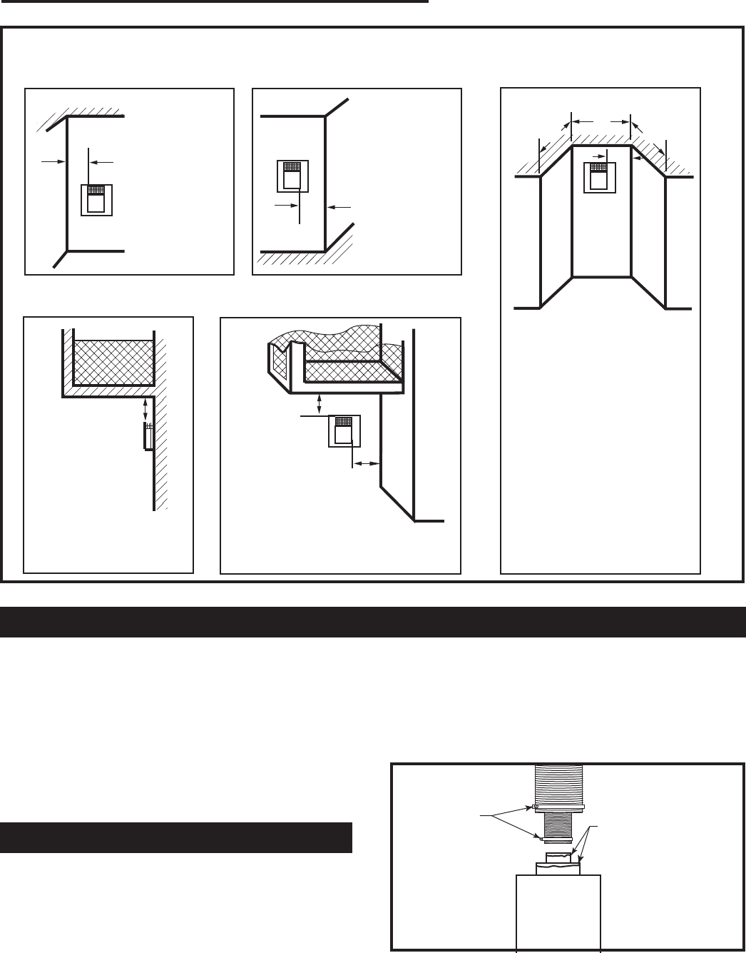
Outside Corner
Inside Corner
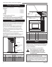
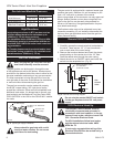
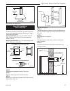
Termination Clearances
Termination clearances for buildings with combustible and noncombustible exteriors.
A =
Combustible
6"(152mm)
Noncombustible
2"(50mm)
B =
Combustible
6"(152mm)
Noncombustible
2"(50mm)
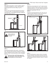
A
Balcony -
with no side wall
G =
Combustible &
Noncombustible
12"(305mm)
G
Balcony -
with perpendicular side wall
H = 24"(610mm)
J = 20"(508mm)
H
J
B
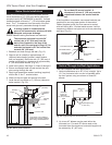
Recessed Location
C = Maximum depth of 48"
(1219mm) for recessed
location.
D = Minimum width for back wall
of a recessed location.
Combustible 38"(965mm)
Noncombustible 24"(610mm)
E = Clearance from corner in
recessed location.
Combustible 6"(152mm)
Noncombustible 2"(50mm)
C
D
C
E
V
V
Combustible &
Noncombustible
V
V
V
General Information Assembling Vent Pipes
Canadian Installations:
Venting system must be installed in accordance with the
current CSA-B149.1 installation code.
USA Installations:
The venting system must conform with local codes and/
or the current National Fuel Gas code ANSI Z223.1/
NFPA 54.
Only venting components manufactured by CFM Corpo
-
ration can be used in Direct Vent systems.
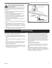
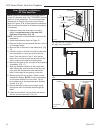
Flex Vent Pipes
Before joining the flex vent pipe to the unit, apply a
bead of high temperature sealant* (provided) to the 4”
pipe exiting the fireplace. Secure flex vent pipe in place
with a hose clamp (provided).
*Be sure the flex pipe overlaps at least 1” (25 mm) onto
the collars of the fireplace and termination. If the ter
-
mination has an internal bead, be sure to overlap and
secure 1” (25 mm) past the bead.
584-15
Fig. 8 Termination clearances.
* Be sure the vent is actually crushed before proceed-
ing. Apply a tug to be sure the vent will not slip off the
collars.
Repeat process with 7” flex vent pipe. The same proce-
dure must be performed on the vent side.
FP1471
flex vent
Hose Clamp
Apply High Tempera
-
ture Sealant
FP1471a
Fig. 9 Apply high temperature sealant to 4” and 7” pipes.