


Special offers from our partners!

Find Replacement BBQ Parts for 20,308 Models. Repair your BBQ today.
19
CDV Series Direct Vent Gas Fireplace
20010175
Example: Maximum horizontal length
0 x 45° elbows = 10’ (3 m)
1 x 45° elbows = 8
¹⁄₂’ (2.6 m)
2 x 45° elbows = 7’ (2.1 m)
3. A minimum of an 8’ vertical rise.
4. Two sets of 45° elbows offsets within these vertical
installations. From 0 to a maximum of 8’ (2.4 m) of
vent pipe can be used between elbows. (Fig. 33)
5. 7DVCS must be used to support offsets. (Fig. 33)
This application will require that you first determine
the roof pitch and use the appropriate 7DVSKV (A, B
or F). (Refer to Venting Components List, Page 27)
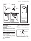
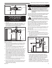
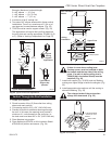
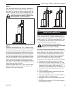
Vertical Through-the-Roof Installation
FP1021
Typical vertical
through the roof
application
3/26/00 djt
Max.
8’
(2.4 m)
45°
Max.
8’
(2.4 m)
45°
50’
(15 m)
Typical
Ceiling
Support
Application
Typical Roof
Support Ap
-
plication
FP1021
Typical Offset Installation
Fig. 33 Typical vertical roof applications.
1. Locate your fireplace.
2. Plumb to center of the (4”) flue collar from ceiling
above and mark position.
3. Cut opening equal to 9
³⁄₈” x 9³⁄₈” (240 x 240 mm).
4. Proceed to plumb for additional openings through
the roof. In all cases, the opening must provide a
minimum of 1 inch clearance to the vent pipe, i.e.,
the hole must be at least 9³⁄₈” x 9³⁄₈” (240 x 240 mm).
5. Place fireplace into position.
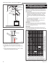
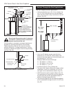
6. Place firestop(s) #7DVFS or Attic Insulation Shield
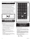
#7DVAIS into position and secure. (Fig. 34)
CFM100
Firestop-Vertical
09/20/00
11"
11"
Joist
Joist
Firestop Spacer
Nails (4)
Upper Floor
Attic Insulation
Shield
Ceiling
Installation
CFM100
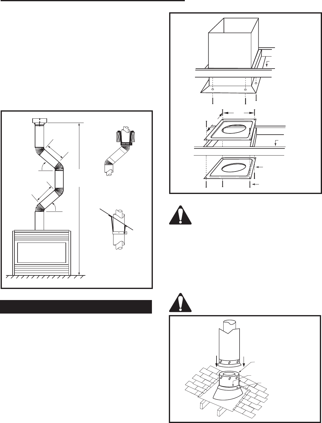
Fig. 34 Place firestop spacer(s) and secure.
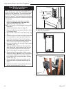
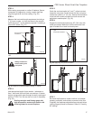
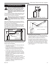
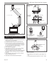
7. Install roof support (Fig. 35 & 36) and roof flashing
making sure upper flange is below the shingles. (Fig.
35)
8. Install appropriate pipe sections until the venting is
above the flashing. (Fig. 35)
If there is room above ceiling level,
firestop spacer must be installed on both
the bottom and the top side of the ceiling
joists. If an attic is above ceiling level a
7DVAIS (Attic Insulation Shield) must be
installed. (Fig. 34)
The enlarged ends of the vent section
always face downward. (Fig. 35)
TWL101a
Twist Lock Pipe
2/8/99 djt
3 #5 Sheet Metal
Screws per Joint
Storm Collar
TWL101a
Fig. 35 Roof flashing.
Sealant