


Special offers from our partners!

Find Replacement BBQ Parts for 20,308 Models. Repair your BBQ today.
6
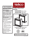
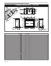
CDV Series Direct Vent Gas Fireplace
20010175
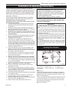
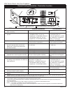
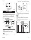
Top of Unit to Ceiling ............................... 36” (914 mm)
Front of Unit to Combustibles .................. 36” (914 mm)
Appliance
Top .......................................................... 0” (0 mm)
Bottom ..................................................... 0” (0 mm)
Side ......................................................... 0” (0 mm)
Back ........................................................ 0” (0 mm)
Venting
Concentric sections of DV Vent
Top, bottom & sides .............................. 1” (25 mm)
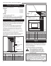
NOTE: Hood must be permanently installed with
three (3) sheet metal screws supplied in fireplace.
A hearth is not mandatory but is recommended for
aesthetic purposes. We recommend a noncombustible
hearth which projects out 12” (305 mm) or more from
the front of the fireplace.
Cold climate installation recommendation:
When installing this unit against a
non-insulated exterior wall or chase,
it is mandatory that the outer walls
be insulated to conform to applicable
insulation codes.
Hearth
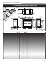
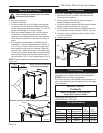
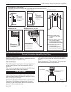
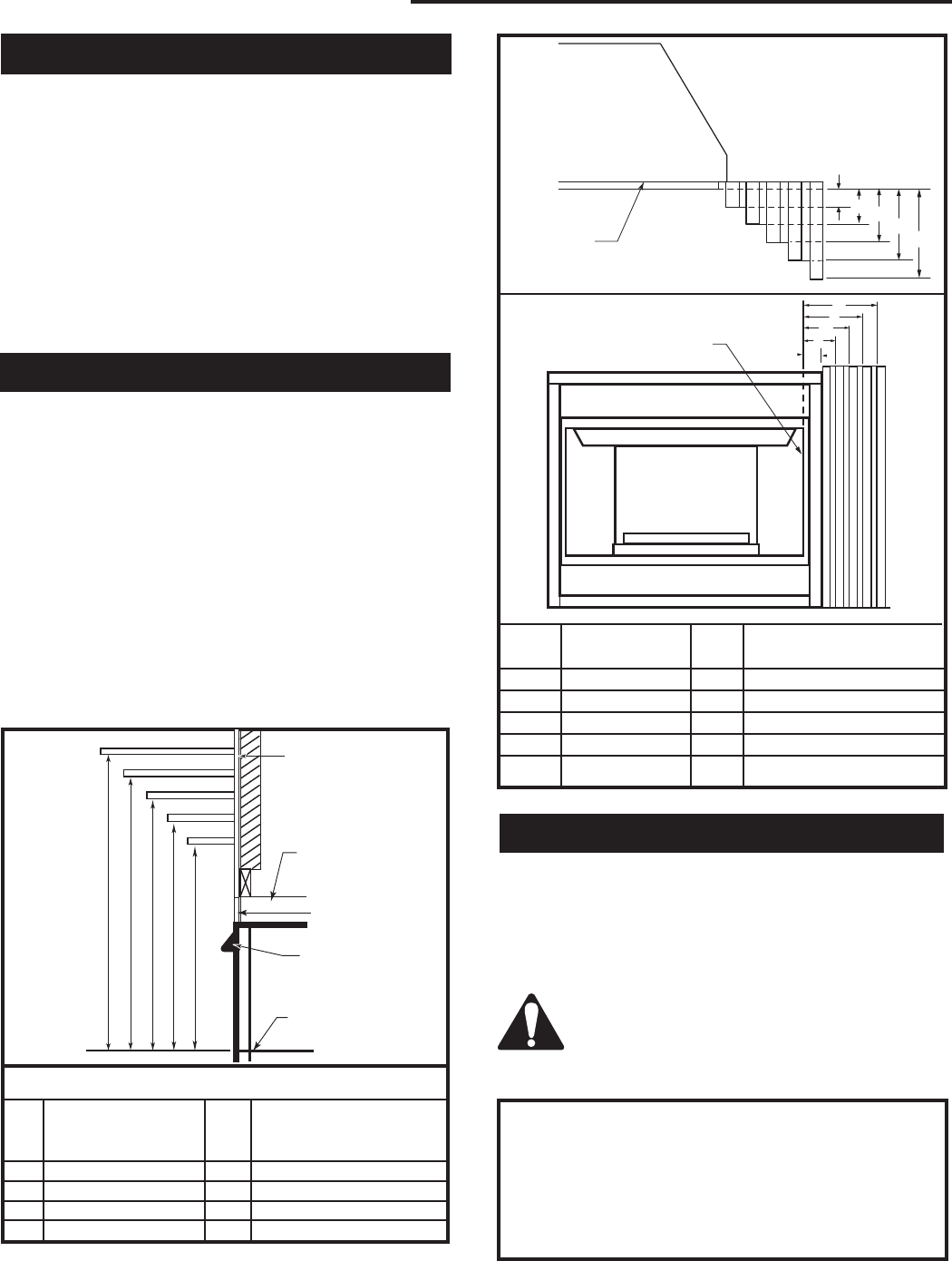
Mantels
The height that a combustible mantel is fitted above the
fireplace is dependent on the depth of the mantel. This
also applies to the distance between the mantel leg (if
fitted) and the fireplace.
For the correct mounting height and widths refer to
Figs. 3a and 3b, and the following Mantel Charts.
The fitting of a bay window trim kit does not effect
the distances and reference points referred to in the
diagram and chart.
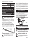
Noncombustible mantels and legs may be installed at
any height and width around the appliance.
When using paint or lacquer to finish the mantel, such
paint or lacquer must be heat resistant to prevent
discoloration.
Clearance to Combustibles
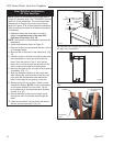
CFM170
J
F
G
H
I
Mantel
Leg
CFM164a
Mantel Leg Chart
06/22/01 sta
Black
Surround
Face
CFM170
DV Builder Front
View
O
N
M
L
K
Side of
Combustion Chamber
CFM164a
Mantel Mantel Leg FromSide
Ref. Leg Depth Ref. of Comb. Opening
F 10” (254 mm) K 11¹⁄₂” (292 mm)
G 8” (203 mm) L 9¹⁄₂” (241 mm)
H 6” (152 mm) M 7¹⁄₂” (191 mm)
I 4” (101 mm) N 5¹⁄₂” (140 mm)
J 2” (51 mm) O 3¹⁄₂” (89 mm)
Fig. 3b Combustible mantel leg minimum installation.
This appliance may be installed in an aftermarket
permanently located, manufactured home or mobile
home, where not prohibited by local codes.
This appliance is only for use with the type of gas indicated
on the rating plate. This appliance is not convertible for
use with other gases, unless a certified kit is used.
The CDVR has been approved for mobile home
installations.
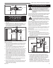
CFM146
A B C D E
V
W
X
Y
Z
Fireplace
CFM146
DV Mantel Chart
7/5/01 sta
Hood
Top of Combustion
Chamber
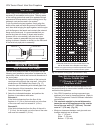
Mantel Chart
Mantel Shelf or Mantel from Top of
Ref. Breast Plate Depth Ref. Combustion Chamber
V 10” (254 mm) A 17” (432 mm)
W 8” (203 mm) B 15” (381 mm)
X 6” (152 mm) C 13” (330 mm)
Y 4” (101 mm) D 11” (279 mm)
Z 2” (51 mm) E 9” (229 mm)
Fig. 3a Combustible mantel minimum installation.
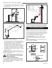
Standoff
Finish Wall
Noncombustible
Material