


Special offers from our partners!

Find Replacement BBQ Parts for 20,308 Models. Repair your BBQ today.
5
W415-0583 / B / 05.23.07
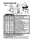
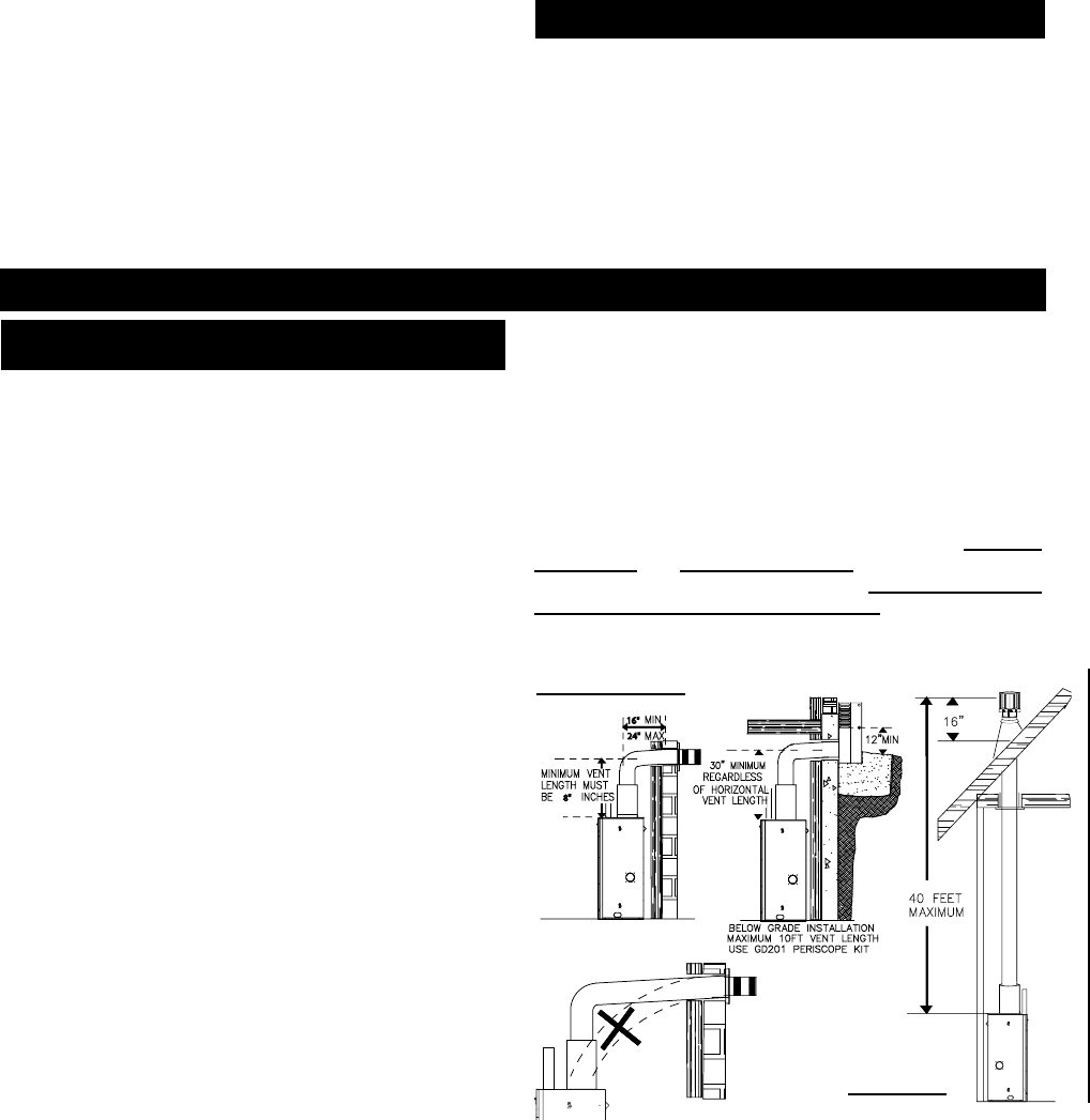
24"
16"
8"
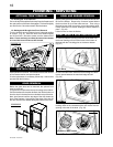
Do not use abrasive cleaners to clean glass. Buff lightly with
a clean dry cloth. The glass is 3/16” ceramic glass available
from your Napoleon® / Wolf Steel Ltd. dealer. DO NOT SUB-
STITUTE MATERIALS. Clean the glass after the fi rst 10 hours
of operation with a recommended gas fi replace glass cleaner.
Thereafter clean as required. DO NOT CLEAN GLASS WHEN
HOT! If the glass is not kept clean permanent discolouration
and / or blemishes may result. Decorative panel may disco-
lour after time.
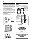
This fi replace may
be installed in an aftermarket permanently
located, manufactured (mobile) home, where not prohibited
by local codes.
This fi replace is only for use with the type of gas indicated
on the rating plate. This fi replace is not convertible for use
with other gases, unless a certifi ed kit is used.
No external electricity (110 volts or 24 volts) is required for
the gas system operation.
Expansion / contraction noises during heating up and cooling
down cycles are normal and are to be expected. Change in
fl ame appearance from “HI” to “LO” is more evident in natural
gas than in propane.
This fi replace is approved for bathroom, bedroom and bed-
sitting room installations and is suitable for mobile home
installation. The natural gas model can only be installed in a
mobile home that is permanently positioned on it’s site
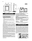
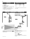
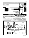
FIGURES 2A-C
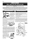
Use only Wolf Steel, Simpson Dura-Vent, Selkirk Direct Temp
or American Metal Amerivent venting components.
Wolf Steel, Simpson Dura-Vent, Selkirk Direct Temp and
American Metal Amerivent venting systems must not be
combined.
Follow the installation procedure provided with the venting
components.
For vent systems that provide seals on the inner exhaust fl ue,
only the outer air intake joints must be sealed using a red high
temperature silicone (RTV). This same sealant maybe used
on both the inner exhaust and outer intake vent pipe joints
of all other approved vent systems except for the exhaust
vent pipe connection to the fi replace fl ue collar which must
be sealed using the black high temperature sealant Mill Pac.
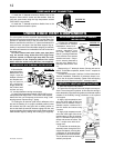
A starter adaptor must be used and may be purchased from
the corresponding supplier:
Supplier 4 / 7
Duravent W175-0053
Amerivent 4DSC-N2
Direct Temp 4DT-AAN
When using Napoleon® venting components, use only
approved Wolf Steel Ltd. rigid / fl exible vent components with
the following termination kits: WALL TERMINAL KIT GD222R,
or 1/12 TO 7/12 PITCH ROOF TERMINAL KIT GD110,
8/12 TO 12/12 ROOF TERMINAL KIT GD111, FLAT ROOF
TERMINAL KIT GD112 or PERISCOPE KIT GD201 (for wall
penetration below grade). With fl exible venting, in conjunction
with the various terminations, use either the 5 foot vent kit
GD220 or the 10 foot vent kit GD330. These vent kits allow
for either horizontal or vertical venting of the fi replace.
The maximum allowable vertical vent length is 40 feet
using fl exible venting. The maximum number of allowable
4” vent connections is three horizontally or vertically
(excluding the fi replace and the air terminal connections).
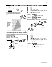
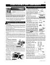
FIGURE 3
CARE OF GLASS
Horizontal runs may have a 0 inch rise per foot in all cases
using SIMPSON DURA-VENT or NAPOLEON® RIGID OR
FLEXIBLE venting components when venting as illustrated
in Figures 2a, 2b, and 2c.
VENTING
VENTING LENGTHS & AIR TERMINAL
LOCATIONS
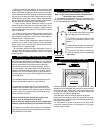
When venting, the horizontal run must be kept to a minimum
of 16 inches or a maximum of 20 feet. If a 20 foot horizontal
run is required, the fi replace must have a minimum vertical rise
immediately off the fi replace of 57 inches. (Fig. 2a-c) When
terminating vertically, the vertical rise is a minimum 34 inches
and a maximum 40 feet above the fi replace. (Fig. 3)
For optimum performance, it is recommended that all
horizontal runs have a minimum ¼ inch rise per foot.
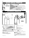
Do not allow the inside liner to bunch up on horizontal or
vertical runs and elbows. Keep it pulled tight. A 1¼” air gap
between the inner and outer liner all around is required for
safe operation.
Use a firestop when penetrating interior walls, floor or
ceiling.
For safe and proper operation of the fi replace follow the
venting instruction exactly.
Deviation from the minimum vertical vent length can create
diffi culty in burner start-up and/or carboning.
Provide a means for visually checking the vent connection to
the fi replace after the fi replace is installed.
Vent lengths that pass through unheated spaces (attics,
garages, crawl spaces) should be insulated with the insulation
wrapped in a protective sleeve to minimize condensation.
The air terminal must remain unobstructed at all times.
Examine the air terminal at least once a year to verify that it
is unobstructed and undamaged.
and fueled with natural gas.
For optimum fl ame appearance and fi replace performance,
keep the vent length and number of elbows to a minimum.
The inner stainless steel looking fi rebox back will discolour
with heat, turning a light brown, straw like colour that is to be
considered normal.