


Special offers from our partners!

Find Replacement BBQ Parts for 20,308 Models. Repair your BBQ today.
11
W415-0583 / B / 05.23.07
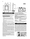
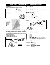
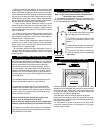
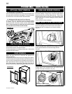
1. Move the fi replace into position.
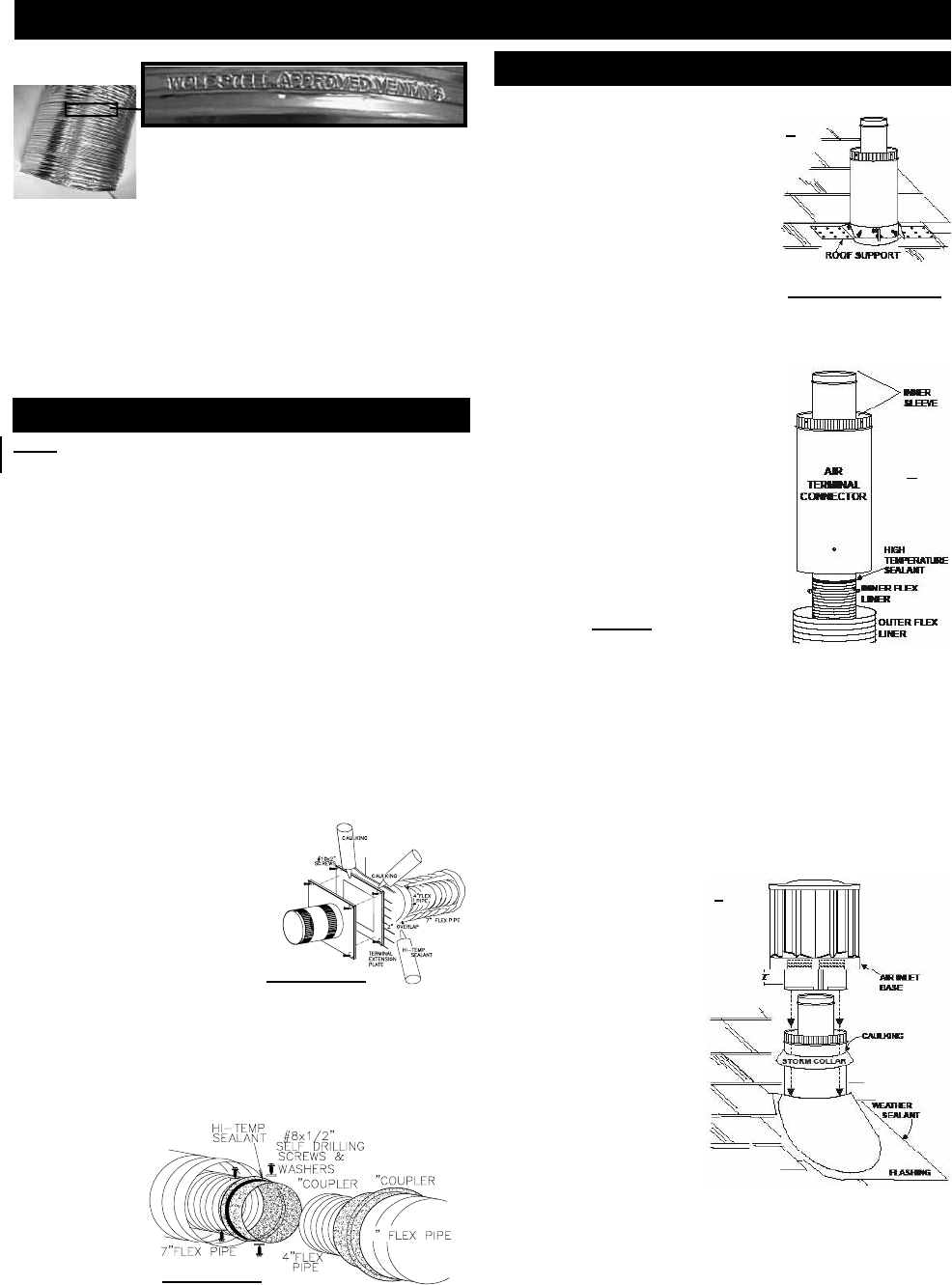
2. Fasten the roof support to the
roof using the screws provided.
The roof support is optional. In this
case the venting is to be adequately
supported using either an alternate
method suitable to the authority
having jurisdiction or the optional roof
support. (Fig.a)
3. Stretch the inner aluminum
fl ex liner to the required length.
Slip the liner a minimum of 2” over the
inner sleeve of the air terminal connector and secure with 3
#8 screws. Seal using a heavy bead of the high temperature
sealant. (Fig.b)
4. Repeat using the outer aluminum
fl ex liner. (Fig.b)
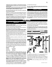
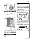
5. Thread the air terminal connector
/ liner assembly down through
the roof. The air terminal must be
located vertically and plumb. Attach
the air terminal connector to the
roof support, ensuring that the top
of the air terminal is 16” above the
highest point that it penetrates the
roof. (Fig.c) If the attic space is
tight, we recommend threading
the Wolf Steel vent pipe collar or
equivalent loosely onto the air
terminal assembly as it is passed
through the attic.
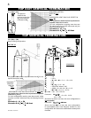
6. Remove nails from the shingles,
above and to the sides of the
chimney. Place the fl ashing over the
air terminal connector leaving a min. 3/4” of the air terminal
connector showing above the top of the fl ashing. Slide
the fl ashing underneath the sides and upper edge of the
shingles. Ensure that the air terminal connector is properly
centred within the fl ashing, giving a 3/4” margin all around.
Fasten to the roof. Do not nail through the lower portion of
the fl ashing. Make weather-tight by sealing with caulking.
Where possible, cover the
sides and top edges of
the fl ashing with roofi ng
material. (Fig.c)
7. Aligning the seams
of the terminal and air
terminal connector, place
the terminal over the air
terminal connector making
sure the liner goes into
the hole in the terminal.
Secure with the three
screws provided. (Fig.c)
8. Apply a heavy bead of
weatherproof caulking 2
inches above the fl ashing.
Note: Maintain a minimum
2” space between the air
inlet base and the storm collar. Install the storm collar around
the air terminal connector and slide down to the caulking.
Tighten to ensure that a weather-tight seal between the air
terminal connector and the collar is achieved. (Fig.c)
Note: Direct vent terminals shall not be recessed into a
wall or siding.
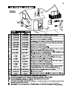
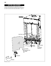
1. Cut or frame a hole in an exterior wall with a minimum
round or square opening of 11
1
/
2
” W x 11
1
/
2
” H if within 24” of
the fi replace collars. If beyond 24” then a 9
1
/
2
” W x 9
1
/
2
” H
opening is acceptable. Secure the fi restop spacer over the
opening to the interior wall.
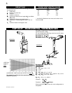
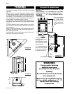
Secure the terminal to the terminal extension plate if required
(see fi gure 18). The cover plate of the GD-222R terminal is
13”x13” and will cover the 11 1/2” x 11 1/2” opening but if the
opening is made any larger - the terminal extension plate is
required.
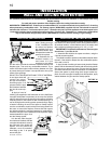
2. Stretch the 4” diameter aluminum fl exible liner to the
required length taking into account the additional length
needed for the fi nished wall surface. Slip the liner a minimum
of 2” over the inner sleeve of the air terminal and secure with
3 #8 screws. Apply a heavy bead of the high temperature
sealant.
3. Using the 7” diameter fl ex-
ible aluminum liner, slide over the
outer combustion air sleeve of the
air terminal and secure with 3 #8
screws. Seal as before.
4. Insert the liners through the
fi restop maintaining the required
clearance to combustibles. Se-
cure to the exterior wall and make
weather tight by sealing with caulking (not supplied).
5. Apply a heavy bead of the high temperature sealant,
(W573-0007 not provided), to the inside of the 4” liner ap-
proximately 1” from the end. Slip the liner a minimum of 2”
over the fi replace vent collar and secure with 3 #8 screws.
6. Using the
7” diameter
fl exible alumin-
ium liner, apply
sealant, slide
a minimum of
2” over the fi re-
place combus-
tion air collar
and secure with 3 #8 screws.
4
7
7
FIGURE 18
Use only approved aluminum fl exible liner kits marked:
“Wolf Steel Approved Venting” as
identifi ed by the stamp only on the 7”
outer liner.
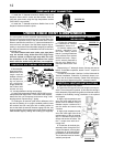
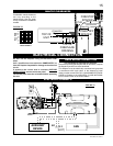
USING FLEXIBLE VENT COMPONENTS
HORIZONTAL AIR TERMINAL INSTALLATION
For safe and proper operation of the fi replace, follow the venting
instructions exactly.
All inner exhaust and outer intake vent pipe joists may be sealed
using either Red RTV high temp silicone sealant or Black high
temp Mill Pac with the exception of the fi replace exhaust fl ue
collar which must be sealed using Mill Pac (not supplied).
VERTICAL AIR TERMINAL INSTALLATION
DO NOT CLAMP THE
FLEXIBLE
ALUMINIUM LINER.
b
c
CAULKING
SCREWS
#10x2"
PIPE
7" FLEX
2" OVERLAP
4"FLEX
PIPE
SEALANT
HI-TEMP
TERMINAL
EXTENSION
PLATE
CAULKING
FIGURE 17
FIGURE 19 a,b&c
a
Spacers are attached to the inner fl ex liner at predetermined
intervals to maintain a 1-1/4” air
gap to the outer fl ex liner.
These spacers must not be removed.