


Special offers from our partners!

Find Replacement BBQ Parts for 20,308 Models. Repair your BBQ today.
10
W415-0583 / B / 05.23.07
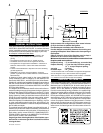
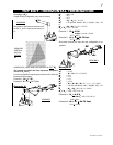
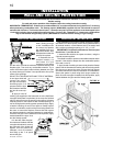
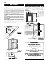
This application occurs
when venting through
a roof. Installation kits
for various roof pitches
are available from your
Napoleon® dealer. See
Accessories to order the
specifi c kit required.
1. Determine the air
terminal location, cut
and frame 11½ inch
openings in the ceiling
and the roof to provide the minimum clearance between the
fi replace pipe / liner and any combustible material. Try to
center the exhaust pipe location midway between two joist
to prevent having to cut them. Use a plumb bob to line up the
center of the openings.
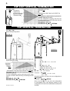
DO NOT FILL THIS SPACE WITH ANY TYPE OF MATERIAL.
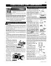
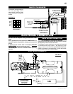
A vent pipe shield will
prevent any materi-
als such as insulation,
from fi lling up the 1" air
space around the pipe.
Nail headers between
the joist for extra sup-
port.
2. Apply a bead of
caulking (not supplied) to the framework or to the Wolf Steel
vent pipe shield plate or equivalent (in the case of a fi nished
ceiling), and secure over the opening in the ceiling. A fi restop
must be placed on the bottom of each framed opening in a
roof or ceiling that the venting system passes through. Apply
a bead of caulking all around and place a fi restop spacer
over the vent shield to restrict cold air from being drawn into
the room or around the fi replace. Ensure that both spacer
and shield maintain the required clearance to combustibles.
Once the vent pipe / liner is installed in its fi nal position, apply
sealant between the pipe / liner
and the fi restop spacer.
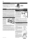
3. In the attic, after the pipe /
liner has been installed, slide the
vent pipe collar down to cover up
the open end of the shield and
tighten. This will prevent any
materials, such as insulation,
from fi lling up the 1" air space
around the pipe.
INSTALLATION
WALL AND CEILING PROTECTION
VERTICAL INSTALLATION
VENT PIPE
SHIELD
VENT
PIPE
COLLAR
FIGURE 15
FIGURE 14
11
11
FIGURE 13
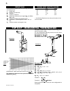
For optimum performance it is recommended that all horizontal runs have a minimum ¼ inch rise per foot using
fl exible venting.
For safe and proper operation of the fi replace, follow the venting instructions exactly.
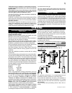
HORIZONTAL TERMINATION: A clearance to combustibles of 2" must be maintained during the fi rst 24” of venting
when penetrating combustible walls. The fi restop spacer (W500-0292) supplied with the unit should be used to
maintain this clearance. The fi rst two feet of outer 7” diameter vent pipe, from the appliance must be wrapped in the
1 inch thick insulation sleeve (supplied) as well as having a 1 inch air gap. Thereafter a 1” clearance to combustibles
may be maintained using fi restop spacer (W615-0044 for use with fl exible venting or rigid venting.)
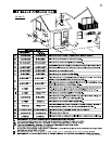
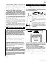
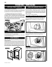
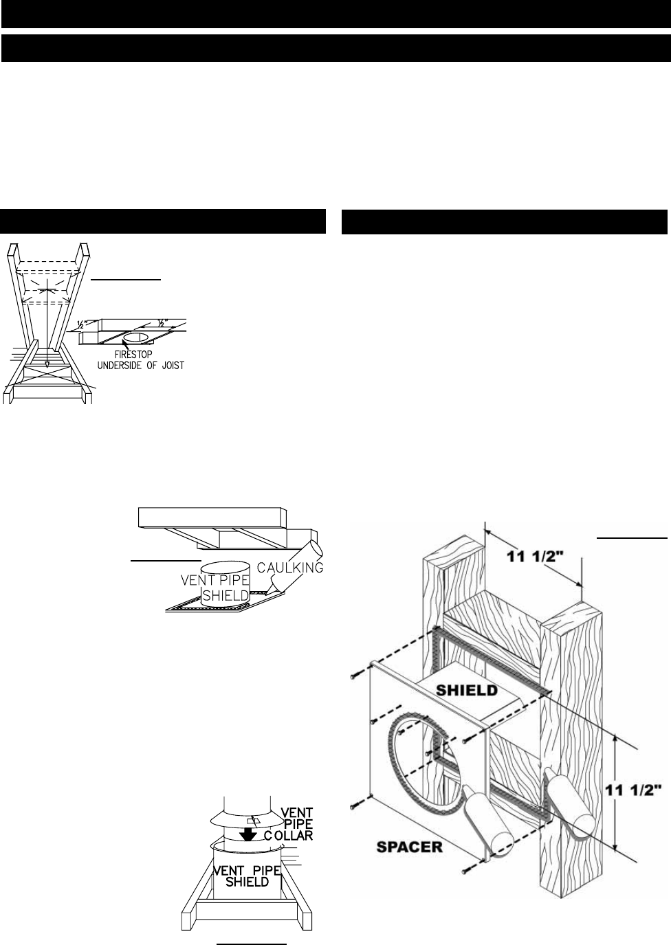
This application occurs when venting through an exterior
wall within 24” of the fi replace collars. Having determined the
air terminal location, cut and frame a hole in an exterior wall
with a minimum rectangle opening of 11 1/2” x 11 1/2”.
IMPORTANT: For optimum performance, The stove pipe
should rise ¼” per foot of run.
1. Assemble the shield to the spacer as shown, using the
3 shorter screws supplied.
The shield is meant to protect combustible materials within
the wall. If the shield is deeper than the combustible portion
of the wall, cut to fi t.
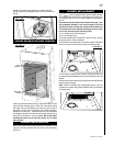
2. Apply a bead of caulking all around and place the fi restop
spacer over the framework to restrict cold air from being drawn
into the room or around the stove. Ensure that both spacer
and shield maintain the required clearance to combustibles.
Secure the spacer in place using the 4 longer screws sup-
plied. Once the vent pipe is installed in its fi nal position, apply
sealant between the pipe and the fi restop spacer.
HORIZONTAL INSTALLATION
FIGURE 16