


Special offers from our partners!

Find Replacement BBQ Parts for 20,308 Models. Repair your BBQ today.

12
W415-0583 / B / 05.23.07
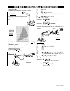
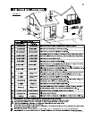
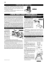
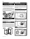
1. Move the fi replace into position.
2. Fasten the roof support to the roof using the screws pro-
vided. The roof support is optional. In this case the venting is
to be adequately supported using either an alternate method
suitable to the authority having jurisdiction or the optional
roof support.
3. Apply high temperature seal-
ant to the outer edge of the inner
sleeve of the air terminal. Slip a 4”
diameter coupler a minimum of 2”
over the sleeve and secure using
3 screws.
4. Apply high temperature seal-
ant to the outer edge of the of the
outside sleeve of the air terminal.
Slip a 7” diameter coupler over the
sleeve and secure as before. Trim
the 7” coupler even with the 4”
coupler end.
5. Thread the air terminal pipe
assembly down through the roof
support and attach, ensuring that
a minimum 16” of air terminal will
penetrate the roof when fastened.
The air terminal must be located
vertically and plumb.
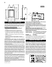
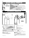
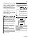
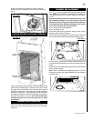
The vent system must be supported approximately every 3
feet for both vertical and horizontal runs. Use Wolf Steel vent
spacers or equivalent every 3 feet and either side of each
elbow to maintain the minimum 1¼” clearance between the
outer and inner vent pipes. Use Wolf Steel support ring as-
sembly or equivalent noncombustible strapping to maintain
the minimum clearance to combustibles for both vertical and
horizontal runs.
All inner exhaust and outer intake vent pipe joists
may be sealed using either Red RTV high temp
silicone sealant or Black high temp Mill Pac with
the exception of the fireplace exhaust flue collar
which must be sealed using Mill Pac (not supplied).
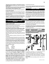
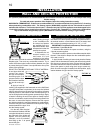
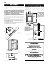
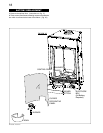
1. Move the fi re-
place into position.
Measure the vent
length required
between terminal
and fi replace tak-
ing into account
the additional
length needed for
the finished wall
surface and any
1¼” overlaps between venting components.
2. Apply high temperature sealant (W573-0007 not pro-
vided) to the outer edge of the 4” inner collar of the fi replace.
Attach the fi rst vent component and secure using 3 self
tapping screws. Repeat using 7” piping.
3. Holding the air terminal (with the air defl ectors to the
top and the lettering in an upright, readable position) insert
the terminal into both vent pipes with a twisting motion to
ensure that both the terminal sleeves engage into the vent
pipes and sealant. Secure the terminal to the exterior wall and
make weather tight by sealing with caulking (not supplied).
1. Install the 4” diameter aluminium fl exible liner to the
fi replace. Secure with 3 screws and fl at washers. Seal the
joint and screw holes using the high temperature sealant
(W573-0007 not provided).
2. Install the 7” diameter aluminium fl exible liner to the
fi replace. Attach and seal the joints.
FIREPLACE VENT CONNECTION
USING RIGID VENT COMPONENTS
HORIZONTAL AIR TERMINAL INSTALLATION
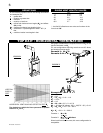
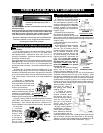
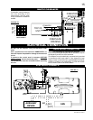
EXTENDED HORIZONTAL AIR TERMINAL
INSTALLATION
FIGURE 20
1. Follow the instructions
for “Horizontal Air Terminal
Installations”, items 1 to 3.
2. Continue adding com-
ponents alternating inner
and outer venting. Ensure
that all 4” venting and elbows
have suffi cient vent spacers
attached and each compo-
nent is securely fastened to
the one prior. Attach the 4”
telescopic sleeve to the vent
run.
Repeat using a 7” telescopic sleeve. Secure and seal as
before. To facilitate completion, attach 4” and 7” couplers to
the air terminal.
3. Install the air terminal. See item 3 of the Horizontal Air
Terminal Installation. Extend the 4” telescopic sleeve; con-
nect to the air terminal assembly. Fasten with self tapping
screws and seal. Repeat using the 7” telescopic sleeve.
HI-TEMP
SEALANT
7" PIPE
2" OVERLAP
4" PIPE
CAULKING
SCREWS
#10x2½"
CAULKING
SEALANT
HI-TEMP
FIGURE 21
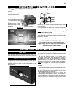
VENTING
TELESCOPIC SLEEVE
20"
COUPLER
AIR TERMINAL
FIGURE 22
VENT PIPE
SHIELD
VENT
PIPE
COLLAR
FIGURE 24
VERTICAL VENTING INSTALLATION
FIGURE 23