


Special offers from our partners!

Find Replacement BBQ Parts for 20,308 Models. Repair your BBQ today.
16
W415-0583 / B / 05.23.07
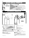
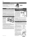
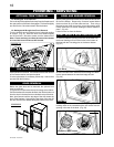
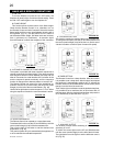
Optional Front
Glass Door
Latches
Retainer
Before the glass door can be removed, the optional front
must be removed.
The glass door is secured to the top front edge of the fi rebox.
Pull the handles of the latches forward, then lift the hooks out
from the slots in the door frame to release the top of the door.
Next, pivot forward until the top edge of the door clears the
front of the fi replace. Next gripping the sides of the door lift
the door out from the retainer along the bottom of the door.
FINISHING / SERVICING
FIGURE 35
DOOR REMOVAL
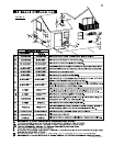
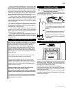
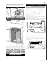
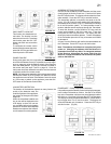
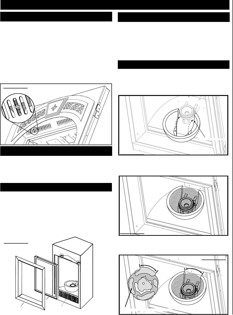
BOWL, MESH & ROCK REPLACEMENT
SCREW W/ SPACER
UNDERSIDE OF ROCK CLUSTER
1. Carefully slide the opening in the rear of the bowl over
the burner making sure to line the holes in the bottom of
the bowl with the 2 locating pins on the burner bottom.
(Fig. 37)
2. Place the steel mesh inside the bowl making sure there
is even space between the mesh and edge of bowl.
(Fig. 38)
3. Carefully place the rocks on the bowl by lining up the
locating notch on the underside of the rock cluster with the
opening in the rear of the bowl. (Fig. 39)
FIGURE 36
FIGURE 37
FIGURE 38
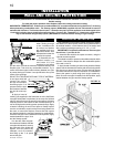
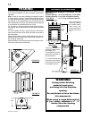
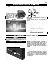
1a. Rectangular Front Removal
Pull on the top of the optional front away from the fi replace until
the male portion of the latch disengages. Tilt forward slightly
and lift from the 2 shoulder screws near the bottom.
1b. Heritage and Wrought Iron Front Removal
Turn the head of each turn button from a horizontal position
to vertical. (Fig. 41) Allow the front to tilt forward slightly
and lift from the 2 shoulder screws near the bottom front.
Note: Fronts are heavy so when the second turn button
is turned the front will want to fall forward.
OPTIONAL FRONT REMOVAL
FIGURE 34
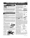
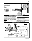
Lift the panel from the slots. This will allow access and removal
of the remote receiver and spark module.
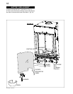
If valve replacement is necessary follow step 1 above then
proceed with the following ...
Start by sliding the bowl forward until it clears the burner then
lift from the fi rebox. Remove the 2 screws located behind
the burner then lift up off the orifi ce and out. Then using a
fl at head screw driver remove the curved decorative panel.
Finally remove the 2 screws holding the burner bottom in
place. (Fig. 42)
Lift the burner out from the fi rebox.
CONTROL PANEL REMOVAL
BOWL AND BURNER REMOVAL